Installation Yamatake Corporation
4-22 ST3000 Smart Transmitter Series 900 Electronic Differential Pressure/Pressure Transmitter
4-4 : Wiring ST 3000 Smart Transmitter
4-4-1 :Wiring for Transmitter -- Regular Model
Introduction
Following wiring instructions when no explosion-proof standards apply.
As well as the following, during wiring and cabling of an explosion-proof transmitter,
refer to the instructions for flameproof special explosion-proof and intrinsically-safe
transmitters (provided later).
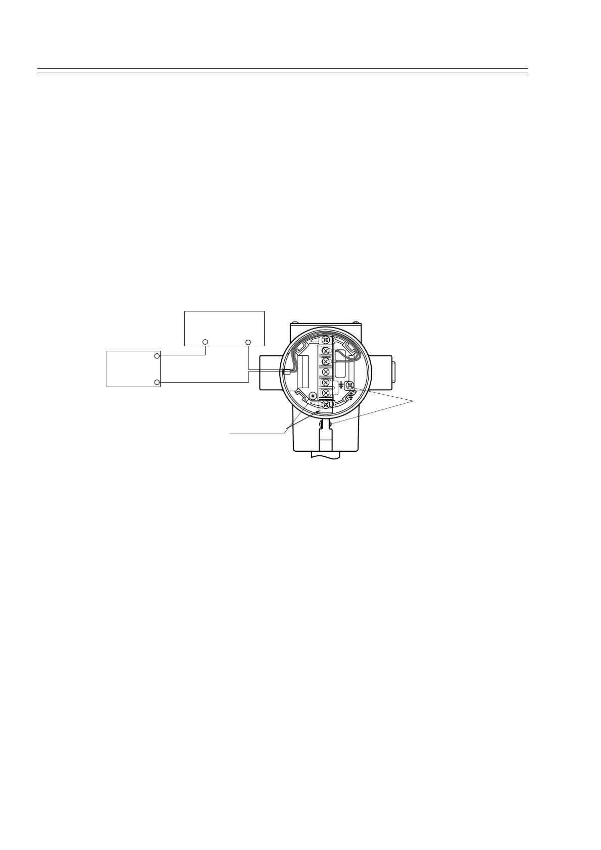
Wire and cable this transmitter as shown in the illustrations.
Figure 4-17 Wiring
~Note 1. External load resistance of at least 250
Ω
required for communications
with an SFC. If total load resistance of the receiving instrument is less
than 250
Ω
, insert the necessary resistance to the loop.
~Note 2. In using Yamateke’s field type indicator (Model NWS300, Model
NWA300), please consult us.
Conduit pipe for cables
Lead cables into the transmitter case, as follows:
Mount a conduit pipe in the conduit hole (1/2NPT female thread) provided on the side
of a transmitter, and lead cables through the pipe.
Seal the part that contacts with the conduit pipe. Use a sealing agent or a seal plug to
prevent entry of water.
Install transmitter so that the cables lead into it, from the bottom.
METER SIGNEL
L
+
ññ
ñ
+ñ
TEST
+
Earth Screw
Terminal Block
DC Power Supply
24W
Receiving
instrument
-
-
+
+