Yamatake Corporation Installation
ST3000 Smart Transmitter Series 900 Electronic Differential Pressure/Pressure Transmitter 4-15
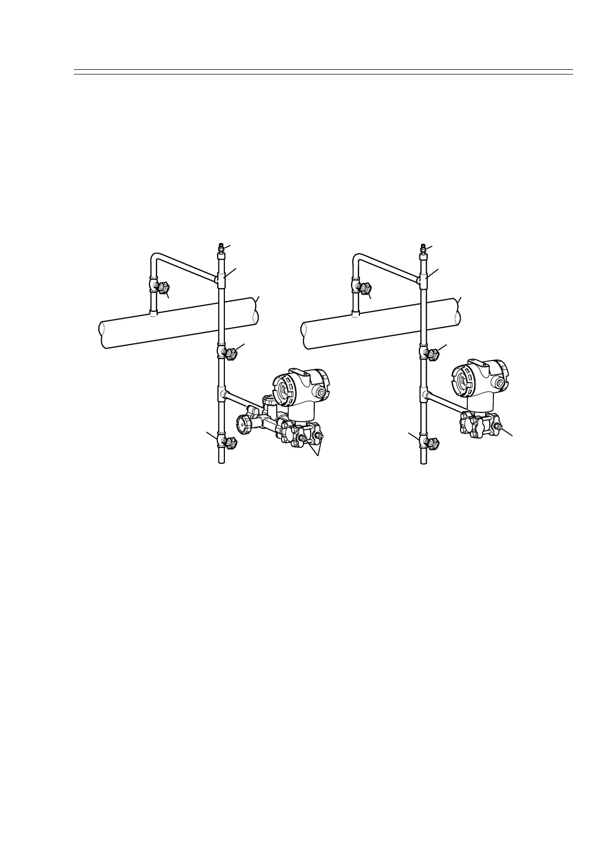
4-3-2 :Pressure Measurement - Piping
Recommended piping - Example
For gas-pressure measurement, piping should be performed following the typical
example shown here. Always observe these points:
At the differential pressure output, make pipe vertical.
After completing piping work, check for pressure leaks around connecting pipe and
transmitter.
Figure 4-11 Gas Pressure Measurement - Piping
Piping method
The piping method for the fluid to be measured depends on the meter installation posi-
tion and the pipe line state. Typical examples of piping are shown in Figure 4-12.
Connect pipes by the following procedure:
(1) Use a T-shaped joint for the connecting pipeline.
(2) Install a main valve between the entrance of the connecting pipe and the T-shaped
joint.
(3) If the process is a horizontal line, tilt the pipe to allow draining from the pressure
line.
~Note In case of a high pressure process, select a joint of appropriate specifica-
tions and shape and a pipe of appropriate shape and material with care.
Gas vent plug
Local valve
Main valve
Drain valve
Vent / Drain plug
Process pipe
Tee
STD type Transmitter
Gas vent plug
Main valve
Local valve
Drain valve
Vent / Drain plug
Process pipe
Tee
STG / STA type Transmitter