Installation Yamatake Corporation
4-14 ST3000 Smart Transmitter Series 900 Electronic Differential Pressure/Pressure Transmitter
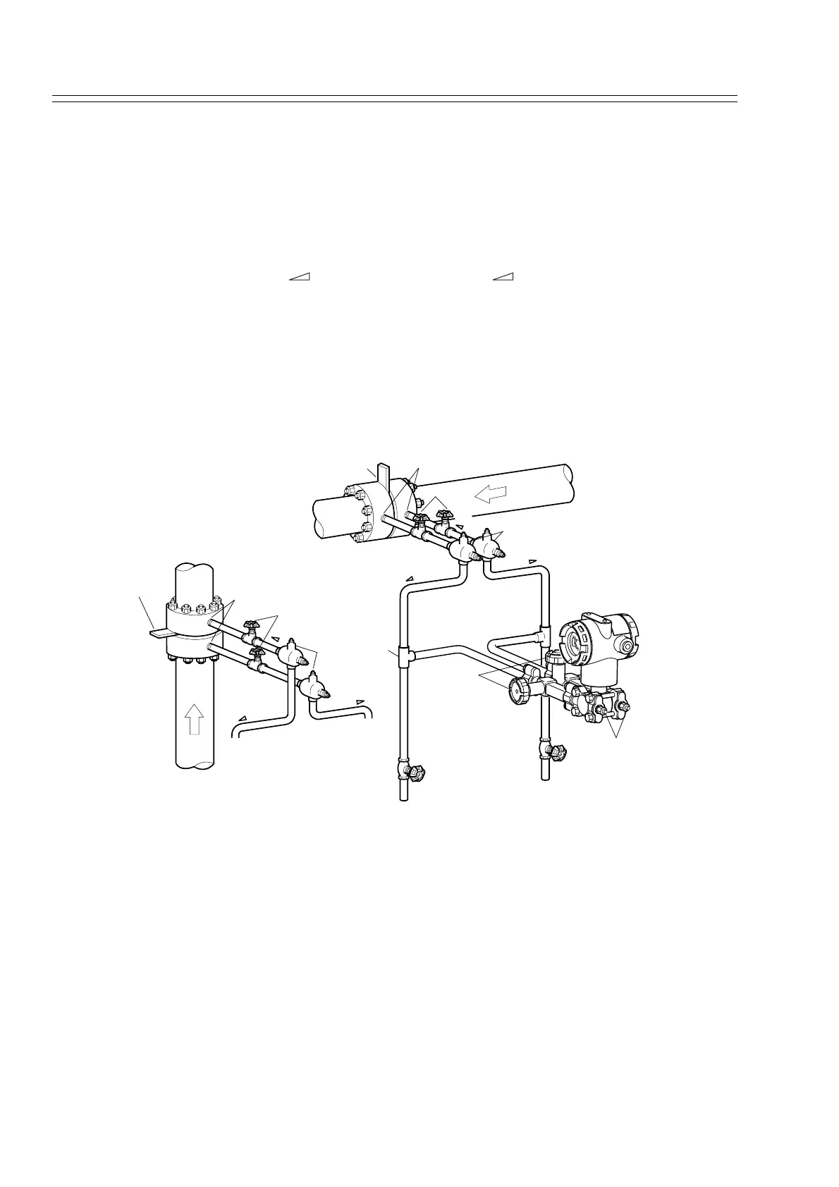
Recommended Piping -- Example 3
The illustration shows a typical example for Steam Flow Rate Measurement. Recom-
mended for a Differential pressure transmitter located below the differential pressure
output port of the process pipe.
The following apply:
Grade the pipe at the differential pressure output part.
Inclination symbol in illustration: Low level High level
After piping work, ensure that the connecting pipe, the 3-way manifold valve, and the
transmitter have no pressure leaks.
If the process pipe is vertically mounted, mount seal pots at different levels to prevent
zero drift. But in this case, you cannot apply the previously-used zero adjustment pro-
cedure (using a 3-way manifold valve). For zero shift occurring at different levels, use
an SFC.
Figure 4-10 Piping for Steam Flow Rate Measurement -- Example
This transmitter is located under the differential pressure output port of the process
pipe.
Orifice
Main valve
Differential pressure output port
Seal pot
High-pressure side
Low-pressure side
Inclination
Inclination
Inclination
3-way
manifold valve
Vent / Drain plug
Drain valve
Drain valve
Tee
Orifice
Main valve
Differential pressure output port
High-pressure side
Low-pressure side
Seal pot
Inclination
Inclination
Inclination