Yamatake Corporation Installation
ST3000 Smart Transmitter Series 900 Electronic Differential Pressure/Pressure Transmitter 4-13
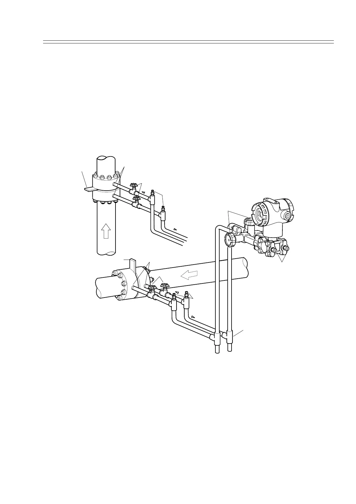
Recommended Piping -- Example 2
The illustration shows a typical example for Gas Flow Rate Measurement. This Differ-
ential pressure transmitter is located above the differential pressure output port of the
process pipe.The condensate drains away from the transmitter.
The following apply:
Grade the pipe at the differential pressure output part.
Inclination symbol in illustration: Low level High level
After piping work, ensure that the connecting pipe, check for pressure leaks around the
3-way manifold valve, and the transmitter.
Figure 4-9 Piping for Gas Flow Rate Measurement -- Example
This transmitter is located above the differential pressure output port of the process
pipe.
Orifice
Differential pressure output port
Main valve
Gas
vent plug
Vent / Drain plug
High pressure side
Low pressure side
3-way manifold valve
Tee
Inclination
Inclination
Orifice
Differential pressure output port
Main valve
Gas vent plug
High pressure side
Low pressure side
Inclination
Inclination