Yamatake Corporation Operation of the Transmitter
ST3000 Smart Transmitter Series 900 Electronic Differential Pressure/Pressure Transmitter 5-63
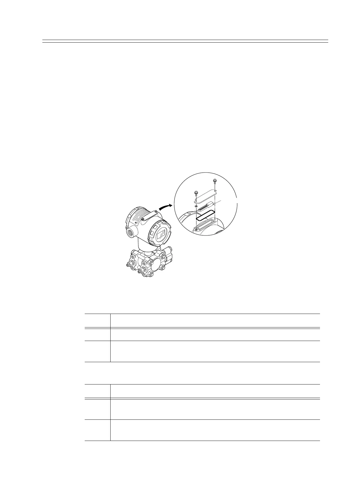
5-12 : External Zero and Span Adjustment (Option)
5-12-1 :External zero and span adjustment
A transmitter with external zero and span adjustment function enables on-site zero/
span point adjustment work without using an SFC.
A transmitter with both a digital meter and external zero and span adjustment function
displays ZERO in the display unit.
Adjustment range
Set to any value an output corresponding to the current input. Set within the range of -
1.25% (3.8 mA) and +105% (20.8 mA).
Procedure
Figure 5-19 External Zero and span Adjustment
How to adjust zero point.
How to adjust span point.
Step Description
1 Make sure that the zero pressure is applied to the transmitter.
2 Insert adjusting magnet into ZERO(+) or (-) cavity in housing and
remove it when ammeter reading equals 4mA.
Step Description
1 Make sure that the desired upper range value pressure is applied to the
transmitter.
2 Insert adjusting magnet into SPAN SET cavity wait until ammeter read-
ing equals 20 mA and remove the magnet from cavity.
Adjusting magnet