Installation Yamatake Corporation
4-4 ST3000 Smart Transmitter Series 900 Electronic Differential Pressure/Pressure Transmitter
Flange mounting
To mount a flange mounted transmitter model, bolt the transmitter’s flange to the
flange pipe on the wall of the tank. Tighten the bolts to a torque of
SNB :
SUS304 :
ATTENTION
On insulated tanks, remove enough insulation to accommodate the flange extension.
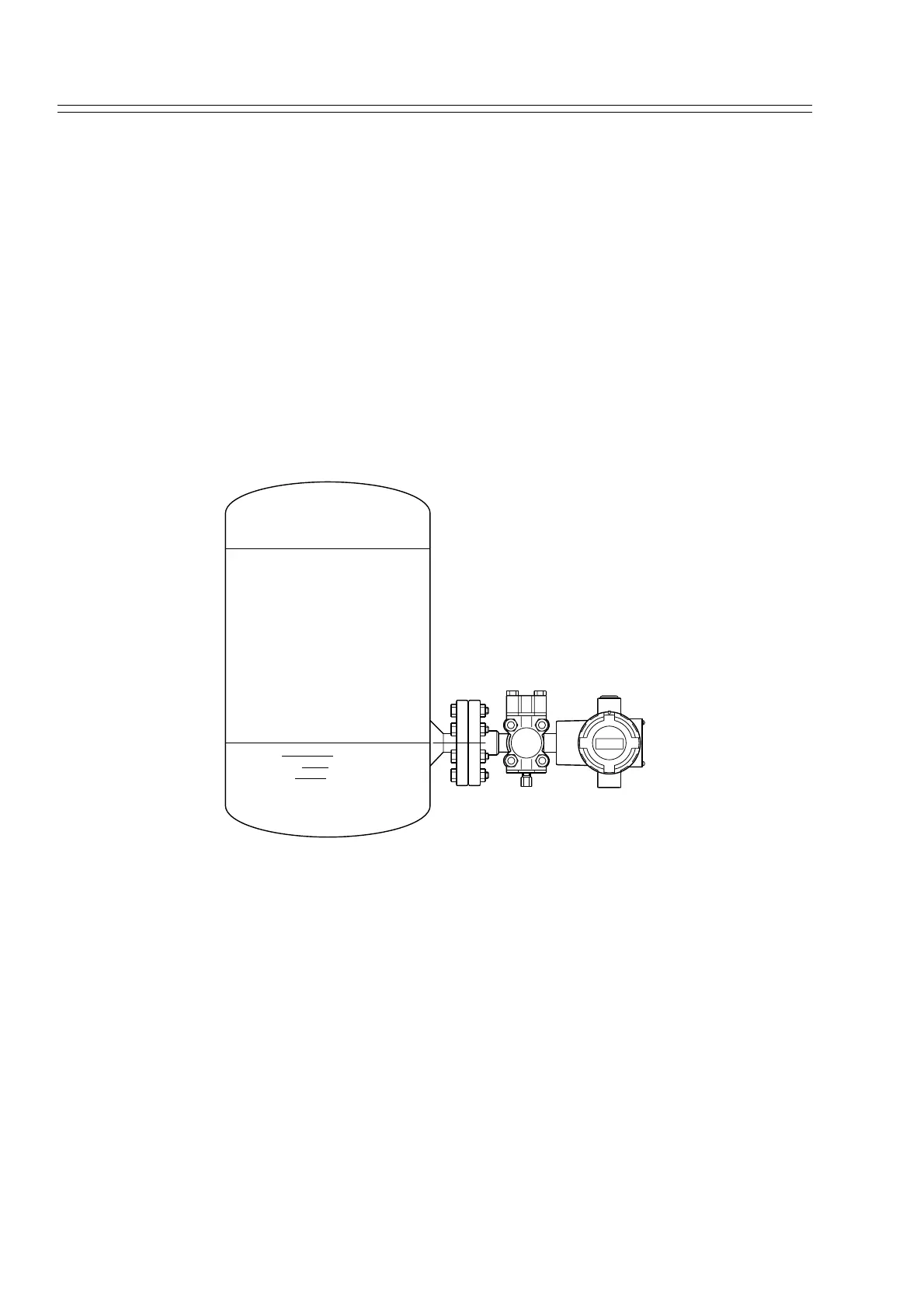
Figure 4-4 shows a typical installation for a transmitter with the flange on the high
pressure (HP) side so the HP diaphragm is in direct contact with the process fluid. The
low pressure (LP) side of the transmitter is vented to atmosphere (no connection).
Figure 4-4 Typical Flange Mounted Transmitter Installation.
20 1± Nm•
10 1± Nm•
100 % Liquid
0 % Liquid