Installation Yamatake Corporation
4-12 ST3000 Smart Transmitter Series 900 Electronic Differential Pressure/Pressure Transmitter
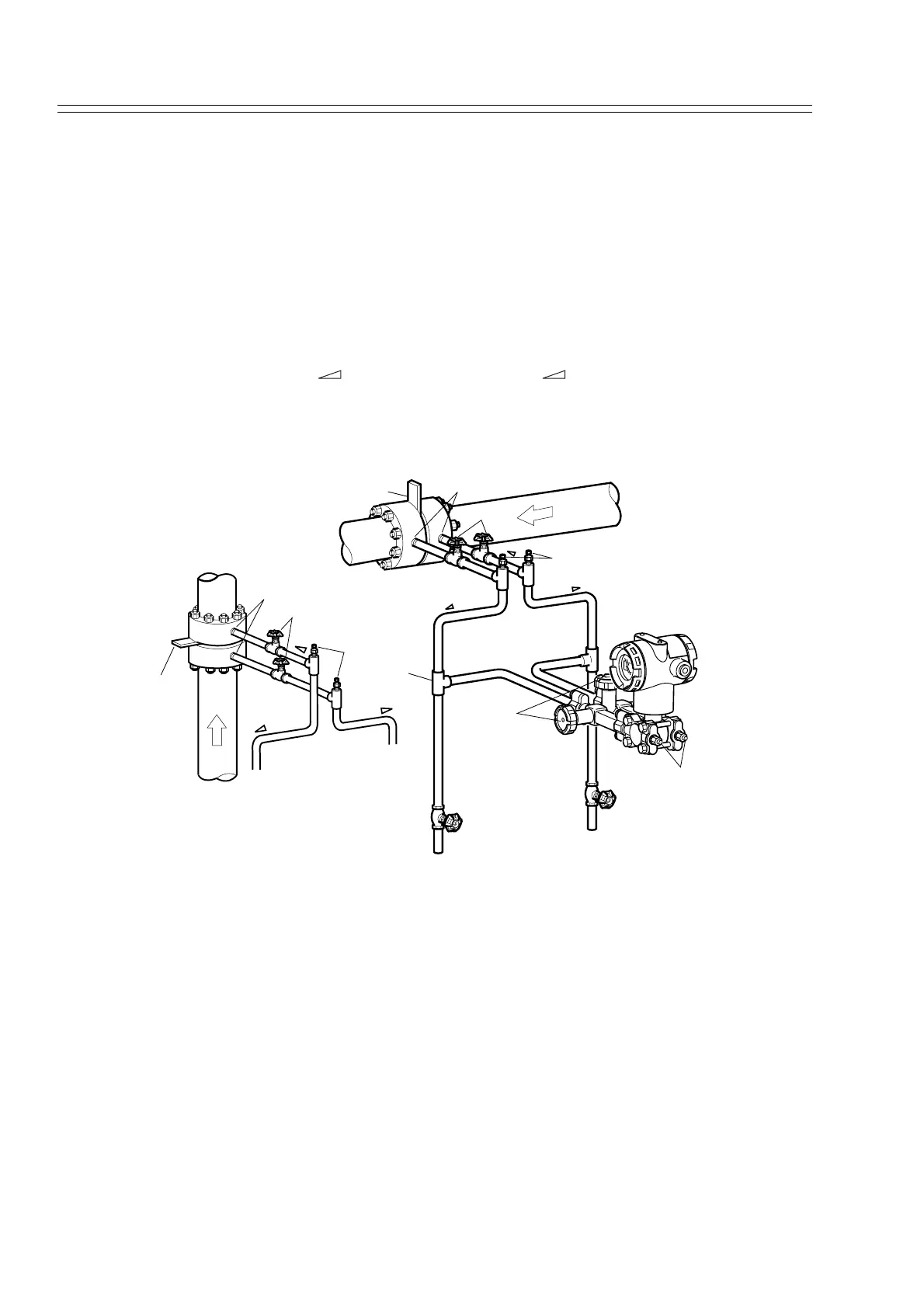
4-3-1 :Piping for Liquid, Gas or Steam Flow Rate Measurement
Recommended Piping -- Example 1
The illustration shows a typical example for liquid Flow Rate Measurement. This Dif-
ferential pressure transmitter is located below the differential pressure output port of
the process pipe.This minimizes the static head effect of the condensate.
The following apply:
Grade the pipe at the differential pressure output part.
Inclination symbol in illustration: Low level High level
After piping work, ensure that the connecting pipe, the 3-way manifold valve, and the
transmitter have no pressure leak.
Figure 4-8 Piping for Liquid Flow Rate Measurement (Example)
This transmitter is located underneath the differential pressure output port of the pro-
cess pipe.
Main valve
Orifice
Gasvent valve
Differential pressure output port
3-way
manifold valve
Low pressure side
High pressure side
Drain valve
Drain valve
Vent / Drain plug
Tee
Inclination
Inclination
Inclination
Differential pressure output port
Orifice
High pressure side
Low pressure side
Main valve
Gas vent valve
Inclination
Inclination
Inclination