Yamatake Corporation Installation
ST3000 Smart Transmitter Series 900 Electronic Differential Pressure/Pressure Transmitter 4-11
Installing flange Adapter
Table 4-4 gives the steps for installing an optional flange adapter on the process head.
Slightly deforming the gasket supplied with the adapter before you insert it into the
adapter may aid in retaining the gasket in the groove while you align the adapter to the
process head. To deform the gasket, submerse it in hot water for a few minutes then
firmly press it into its recessed mounting groove in the adapter.
Table 4-4 Installing Adapter Flange
Step Action
1 Carefully seat FEP (white) gasket into adapter groove.
2 Thread adapter onto 1/2 inch process pipe and align mounting holes in
adapter with holes in end of process head as required.
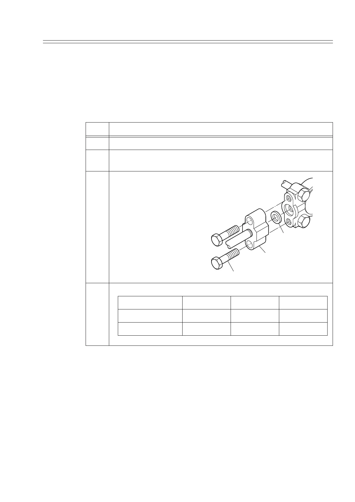
3 Secure adapter to process head
by hand tightening 7/16-20
UNF hexhead bolts.
Example-Installing adapter on
process head
ATTENTION
Apply an anti-seize compound
on the stainless steel bolts prior
to threading them into the pro-
cess head.
4 Evenly tighten adapter bolts to the following torque;
Adapter material CS/SS CS/SS PVC
Bolt material SNB7/SS630 SS304 SNB7/SS304
Torque N•m 20 ±1 10 ±0.5 7 ±0.5
7/16 X 20 UNF Bolts
Adapter Flange
FEP Gasket
Proces
Head