4.4 MP2000 Series Machine Controller Parameter Details
4.4.1 Motion Fixed Parameter Details
4-22
( 6 ) Software Limits
Outline of Software Limit
The software limit function is enabled only after completing a Zero Point Return or Zero Point Setting operation
(IW0C, bit 5 is ON).
For details, refer to 11.3 Software Limit Function.
No. 12
Positive Software Limit Value
Setting Range Setting Unit Default Value
-2
31
to 2
31
−1
User unit
2
31
−1
Description
Set the position to be detected for the software limit in the positive direction at the Machine Controller.
If an axis attempts to move in the positive direction past the position set here, a positive direction software limit alarm
(IL04, bit 3) will occur.
Enabled when bit 1 of the Soft Limit (Positive Direction) Enabled/Disabled (fixed parameter 1, bit 1) is set to 1 (enabled).
No. 14
Negative Software Limit Value
Setting Range Setting Unit Default Value
-2
31
to 2
31
−1
User unit
-2
31
Description
Set the position to be detected for the software limit in the negative direction at the Machine Controller.
If an axis attempts to move in the negative direction past the position set here, a negative direction software limit alarm
(IL04, bit 4) will occur.
Enabled when bit 2 of the Soft Limit (Negative Direction) Enabled/Disabled (fixed parameter 1, bit 2) is set to 1
(enabled).
Bit 1 0: Disabled
1: Enabled
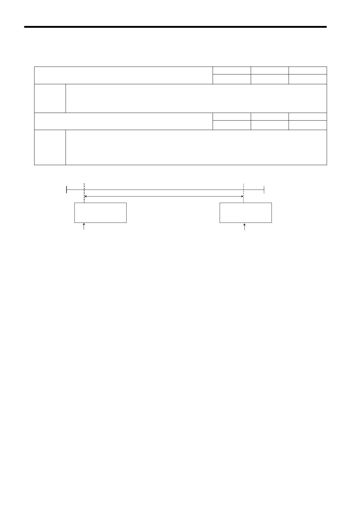
Soft Limit
(Negative Direction)
Enabled/Disabled
Soft Limit
(Positive Direction)
Enabled/Disabled
Range of machine movement
No. 1: Function Selection Flag 1
Bit 2 0: Disabled
1: Enabled
No. 1: Function Selection Flag 1
 Loading...