4.4 MP2000 Series Machine Controller Parameter Details
4.4.2 Motion Setting Parameter Details
4-31
• Operation
To repeat latch operations, set bit 4 of OW00 to 1.
For usual latch operations, IW44 and IW45 are set to 0.
[ c ] Continuous Latch Operation
For continuous latch operations, bit 2 of IW0C is set to 1. With this setting, however, the parameters IL18,
IW44, and IW45 are updated when latching, so the completion of latching can be checked with those parame-
ters.
If checking the completion with bit 2 of IW0C, reset the bit settings with the following procedures.
• When bit 2 of IW0C is detected as 1, set bit D of OW00 to 1 to clear the Latch Complete bit.
Precautions
When continuous latching is done for a short time, the sign of latch completion may not be detected because the update of the
communication cycle or H scan cycle is delayed.
To check if the latch was successfully completed, use IW44 or IW45.
If the current value is one greater than that of the previous cycle, then latching was successfully completed.
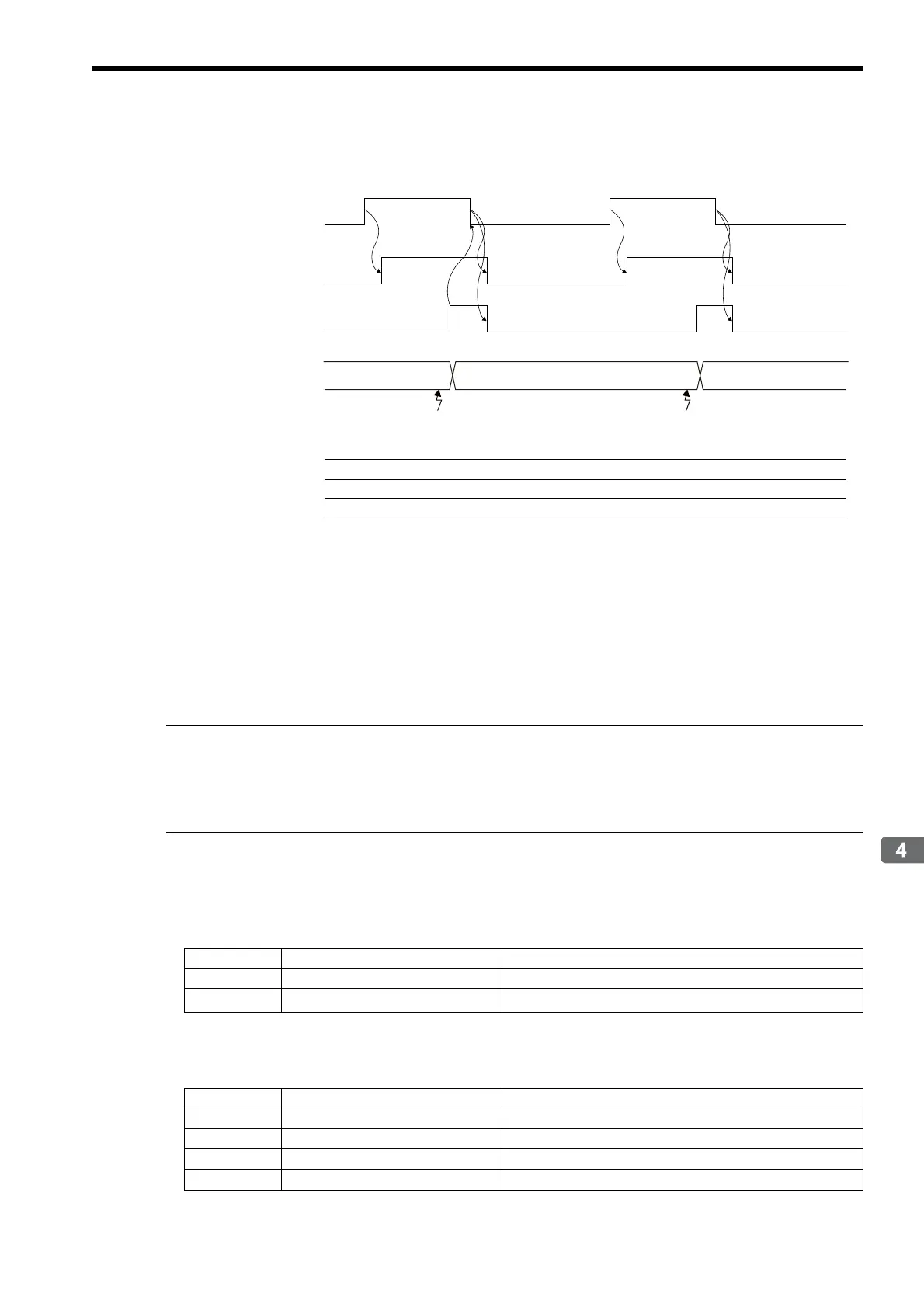
Example 1
• Condition: Latch at phase-C pulse
• Settings:
Motion setting parameters
* When using a continuous latch, the settings of bits 0 to 3 are disabled.
Servo parameters
A square () indicates an unspecified value.
Machine Coordinate
System Latch Position
IL18
Number of Continuous
Latch Sequence
Completion Cycles
IW45
Latch Completion
Sequence Number
IW44
Latch Complete
IW0C.bit 2
Latch Mode
IW00.bit 4
Latch Detection Demand
OW00.bit 4
0
0
LatchLatch
Register No. Name Setting value
OW01
Mode Setting 1 Bit 6: Latch mode selection = 1 (Continuous latch)
OW04
Function Setting 2
Bits 0 to 3: Latch detection signal selection = Disabled
*
Parameter No. Name Setting value
Pn850
Latch Sequence Number 1
Pn851
Continuous Latch Count 0 (No limit)
Pn852
Latch Sequence Signal 1 to 4 Setting
0h
Pn853
Latch Sequence Signal 5 to 8 Setting
h
 Loading...