4.4 MP2000 Series Machine Controller Parameter Details
4.4.2 Motion Setting Parameter Details
4-32
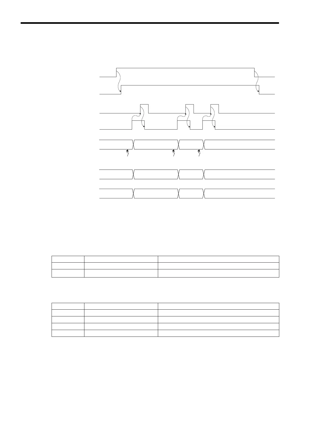
• Operation
For continuous latch operations, bit 4 of OW00 is set to 1. After the latch has been confirmed as being com-
pleted, set bit 10 of OW00 to 1 and bit 2 of IW0C is forced OFF.
Example 2
• Condition: Sequence latch at phase-C pulse and EXT1 signal
• Settings:
Motion setting parameters
* When using a continuous latch, the settings of bits 0 to 3 are disabled.
Servo parameters
A square () indicates an unspecified value.
Register No. Name Setting value
OW01
Mode Setting 1 Bit 6: Latch mode selection = 1 (Continuous latch)
OW04
Function Setting 2
Bits 0 to 3: Latch detection signal selection = Disabled
*
Parameter No. Name Setting value
Pn850
Latch Sequence Number 2
Pn851
Continuous Latch Count 0 (No limit)
Pn852
Latch Sequence Signal 1 to 4 Setting 10h
Pn853
Latch Sequence Signal 5 to 8 Setting h
Machine Coordinate
System Latch Position
IL18
Number of Continuous
Latch Sequence
Completion Cycles
IW45
Latch Completion
Sequence Number
IW44
Latch Complete
IW0C.bit 2
Latch Mode
IW00.bit 4
Latch Detection Demand
OW00.bit 4
11 1
12
Latch LatchLatch
Latch Completion Status
Clear Request
OW00.bit D
3
 Loading...