4-34
Protection Function Parameters: L
Motor Overload: L1
Power Loss Ridethrough: L2
* 1. These are values for a 200 V class Inverter. The value for a 400 V class Inverter is the double.
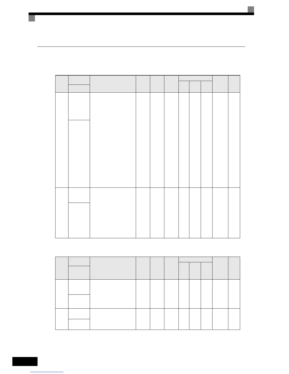
Param-
eter
Number
Name
Description
Setting
Range
Factory
Setting
Change
during
Opera-
tion
Control Methods
MEMO-
BUS
Register
Page
V/f
Open
Loop
Vector
Closed
Loop
Vector
Display
L1-01
Motor pro-
tection selec-
tion
Sets whether the motor thermal
overload protection function is
enabled or disabled.
0: Disabled
1: General-purpose motor
protection (fan cooled
motor)
2: Inverter motor protection
(externally cooled motor)
3: Vector motor protection
When the Inverter power
supply is turned off, the
thermal value is reset, so
even if this parameter is set
to 1, protection may not be
effective.
When several motors are con-
nected to one Inverter, set to
L1-01 to 0 and ensure that each
motor is installed with a pro-
tection device.
0 to 3 1 No Q Q Q 480H 5-38
MOL Fault
Select
L1-02
Motor pro-
tection time
constant
Sets the electric thermal detec-
tion time in seconds units.
Usually changing this setting is
not necessary.
The factory setting is 150%
overload for one minute.
When the motor's overload
capability is known, also set
the overload resistance protec-
tion time for when the motor is
hot started.
0.1 to
5.0
1.0 min No A A A 481H 5-38
MOL Time
Const
Param-
eter
Number
Name
Description
Setting
Range
Factory
Setting
Chang
e dur-
ing
Opera-
tion
Control Methods
MEMO-
BUS
Regis-
ter
Page
V/f
Open
Loop
Vector
Closed
Loop
Vector
Display
L2-05
Undervolt-
age detec-
tion level
Sets the DC bus undervoltage
(UV) detection level (DC bus
voltage).
Usually changing this setting is
not necessary.
150 to
210
*1
190 V
*1
No A A A 489H -
PUV Det
Level
L2-11
Battery Volt-
age
Sets the battery voltage.
0 to 400
*1
0V
*1
No A A A 4CBH -
Battery Volt-
age
http://nicontrols.com