5-44
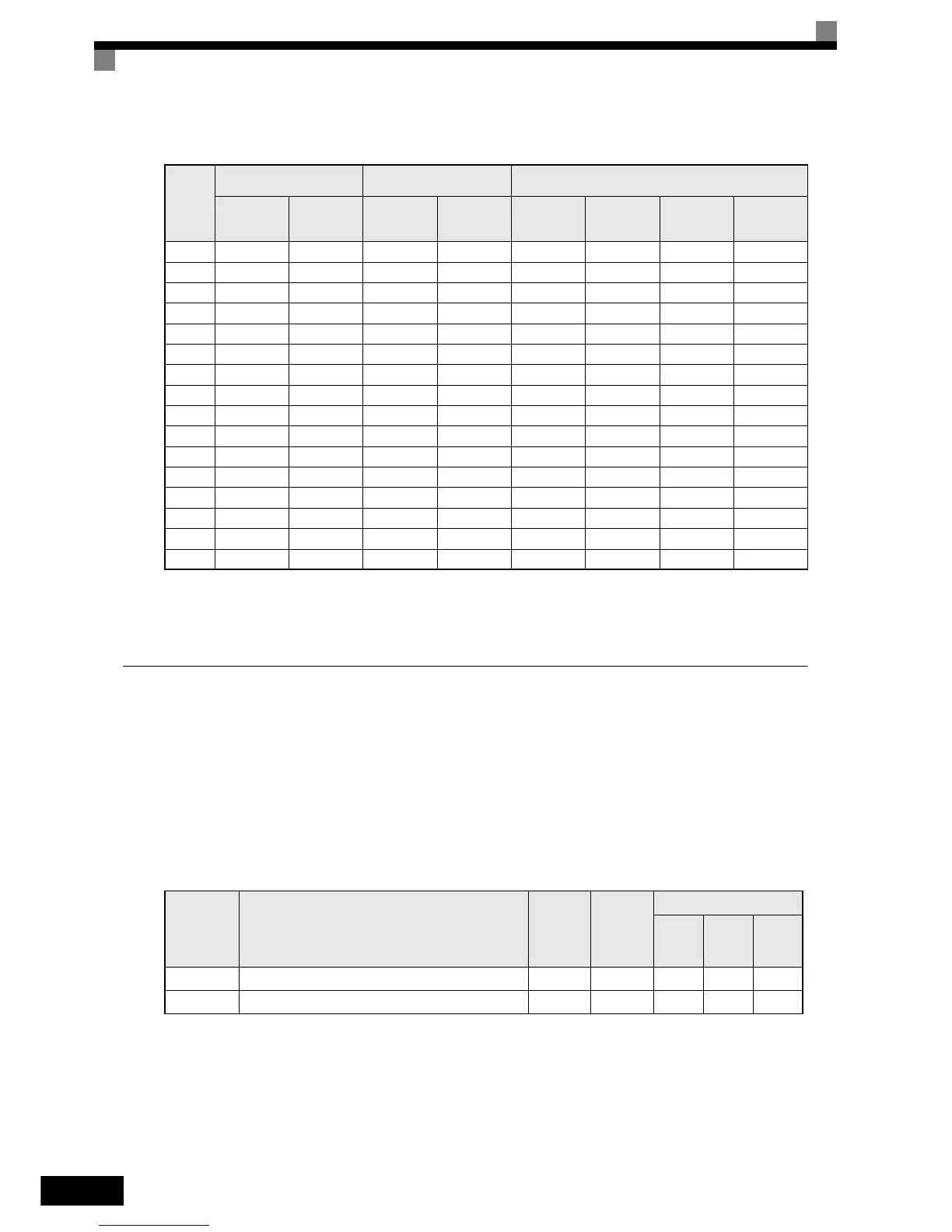
The following table shows the relationship between the external fault conditions and the set value in H1-.
1. Sets the input level at which errors are detected. (NO contact: External error when ON; NC contact: External error when OFF).
2. Set the detection method to detect errors using either constant detection or detection during operation.
Constant detection: Detects while power is supplied to the Inverter.
Detection during operation: Detects only during Inverter operation.
Using the Timer Function
The multi-function digital input terminals S3 to S7 can be used as timer function input terminals, and
multi-function output terminals M1-M2, M3-M4, and M5-M6 can be used as timer function output terminals.
By setting the delay time, you can prevent chattering of the sensors and switches.
• Set one of the parameters H1-01 to H1-05 (digital input terminal S3 to S7) to 18 (timer function input).
• Set H2-01 to H2-03 (multi-function output terminals M1-M2, M3-M4, and M5-M6 function selection) to
12 (timer function output).
Related Parameters
Set
Value
Input Level
(See Note 1.)
Error Detection Method
(See Note 2.)
Operation During Error Detection
NO Contact NC Contact
Constant
Detection
Detection
During Oper-
ation
Decelerate to
Stop (Error)
Coast to Stop
(Error)
Emergency
Stop (Error)
Continue
Operation
(Warning)
20 Yes Yes Ye s
21 Yes Yes Yes
22 Yes Yes Yes
23 Yes Yes Yes
24 Yes Yes Yes
25 Yes Yes Yes
26 Yes Yes Yes
27 Yes Yes Yes
28 Yes Yes Yes
29 Yes Yes Yes
2A Ye s Yes Yes
2B Yes Yes Yes
2C Ye s Yes Yes
2D Yes Yes Yes
2E Yes Yes Ye s
2F Yes Yes Yes
Parameter
No.
Name
Factory
Setting
Change
during
Operation
Control Methods
V/f
Open
Loop
Vector
Closed
Loop
Vector
b4-01 Timer function ON-delay time 0.0 s No A A A
b4-02 Timer function OFF-delay time 0.0 s No A A A
http://nicontrols.com