5-6
Speed Selection Sequence Using Digital Inputs
If the digtal inputs are used for speed selection, the speed selection method and the speed priority depends on
the setting of parameter d1-18.
Multi-Step Speed Operation (Binary Input) (d1-18=0)
Maximum 8 preset speed steps can be selected using 3 binary coded digital inputs. The inverter is started using
the Forward/Reverse command. It stops when the Forward/Reverse command is removed.
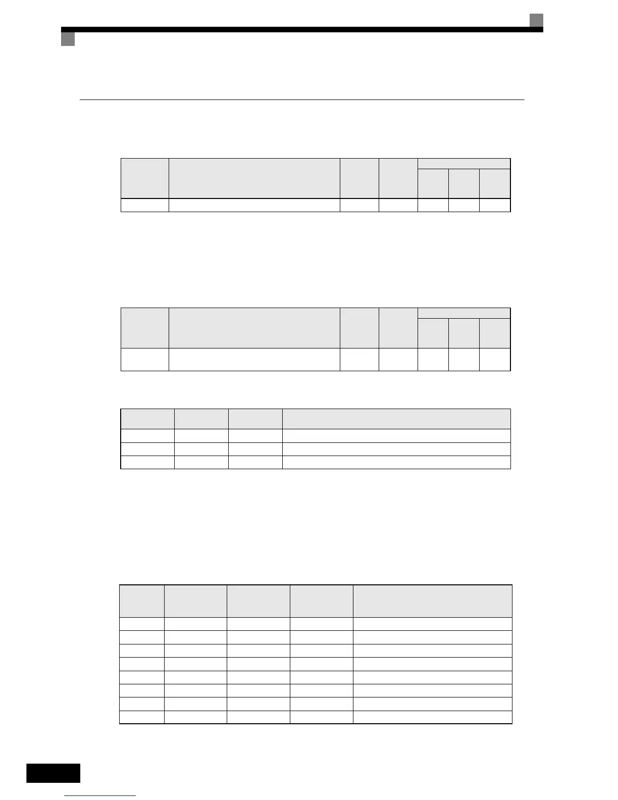
Related Parameters
Multi-function Digital Input Settings (H1-01 to H1-05) (Example)
Speed Selection Table
The following table shows the combinations of the digital input and the according speed.
If b1-02 is set to “1”, speed 1 is input as analog reference at terminal A1 or Channel CH1 of an analog input
option card AI-14B if it is installed.
If an AI-14B option card is used and the function for channel 2 and 3 is set for “Auxiliary Frequency 2”
(H3-05/09=2) and “Auxiliary Frequency 3” (H3-05/09=3) the speeds 2 and 3 are set at the CH2 and CH3 input
of the option card.l
Parameter
No.
Name
Factory
Setting
Change
during
Operation
Control Methods
V/f
Open
Loop
Vector
Closed
Loop
Vector
d1-18 Speed Priority Selection 0 No Q Q Q
Parameter
No.
Name
Factory
Setting
Change
during
Operation
Control Methods
V/f
Open
Loop
Vector
Closed
Loop
Vector
d1-01 to
d1-08
Multi-Step speed 1 to 8 reference value 0.00 Hz Yes A A A
Terminal
Parameter
Number
Set Value Details
S4 H1-02 3 Multi-step speed command 1
S5 H1-03 4 Multi-step speed command 2
S6 H1-04 5 Multi-step speed command 3
Speed
Multi-step Speed
Command 1
Multi-step Speed
Command 2
Multi-step Speed
Command 3
Selected Frequency
1 OFF OFF OFF Frequency reference 1 d1-01 or A1/AI-14B CH1
2 ON OFF OFF Frequency reference 2 d1-02 or AI-14B CH2
3 OFF ON OFF Frequency reference 3 d1-03 or AI-14B CH3
4 ON ON OFF Frequency reference 4 d1-04
5 OFF OFF ON Frequency reference 5 d1-05
6 ON OFF ON Frequency reference 6 d1-06
7 OFF ON ON Frequency reference 7 d1-07
8 ON ON ON Frequency reference 8 d1-08
http://nicontrols.com