5-62
PG Interface
To get a more precise speed control the inverter has PG interface to connect a pulse generator.
Related Parameters
Setting Number of PG Pulses (F1-01)
Set the number of PG (Pulse Generator/Encoder) pulses in pulses per revolution.
Suit the PG Rotation Direction and Motor Rotation Direction (F1-05)
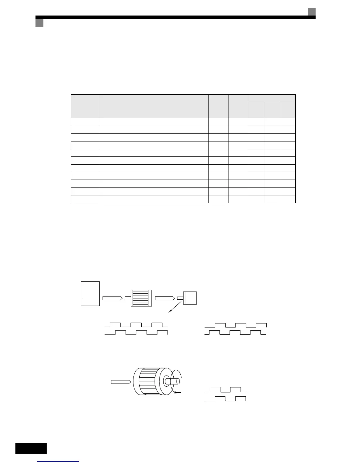
Parameter F1-05 suits the PG rotation direction to the motor rotation direction. If the motor is rotating for-
wards, set whether it is A-phase leads or B-phase leads.
Generally, the A-phase leads when the rotation direction is counter-clockwise (CCW) seen from the shaft side
(FWD command is input).
Parameter
No.
Name
Factory
Setting
Change
during
Opera-
tion
Control Methods
V/f
Open
Loop
Vector
Closed
Loop
Vector
F1-01 PG constant 1024 No No No Q
F1-02 Operation selection at PG open circuit (PGO) 1 No No No A
F1-03 Operation selection at overspeed (OS) 1 No No No A
F1-04 Operation selection at deviation (DEV) 3 No No No A
F1-05 PG rotation 0 No No No Q
F1-06 PG division rate (PG pulse monitor) 1 No No No A
F1-08 Overspeed (OS) detection level 115% No No No A
F1-09 Overspeed detection delay time (OS) 1.0 s No No No A
F1-10 Excessive speed deviation (DEV) detection level 10% No No No A
F1-11 Excessive speed deviation detection delay time (DEV) 0.5 s No No No A
F1-14 PG open-circuit detection delay time 2.0 s No No No A
Inverter
Forward
command
Motor PG (encoder)
Pulse output
A-phase leads when set value = 0
B-phase leads when set value = 1
A-phase A-phase
B-phase
B-phase
Example: Forward rotation of standard motor (PG)
Forward
command
Motor output axis rotates
counter-clockwise during In-
verter forward command.
Rotation
(CCW)
A-phase
B-phase
With the used PG the A-phase leads (CCW) when motor rotation is forward.
http://nicontrols.com