Wiring Control Circuit Terminals
2-21
2
Control Circuit Terminal Functions
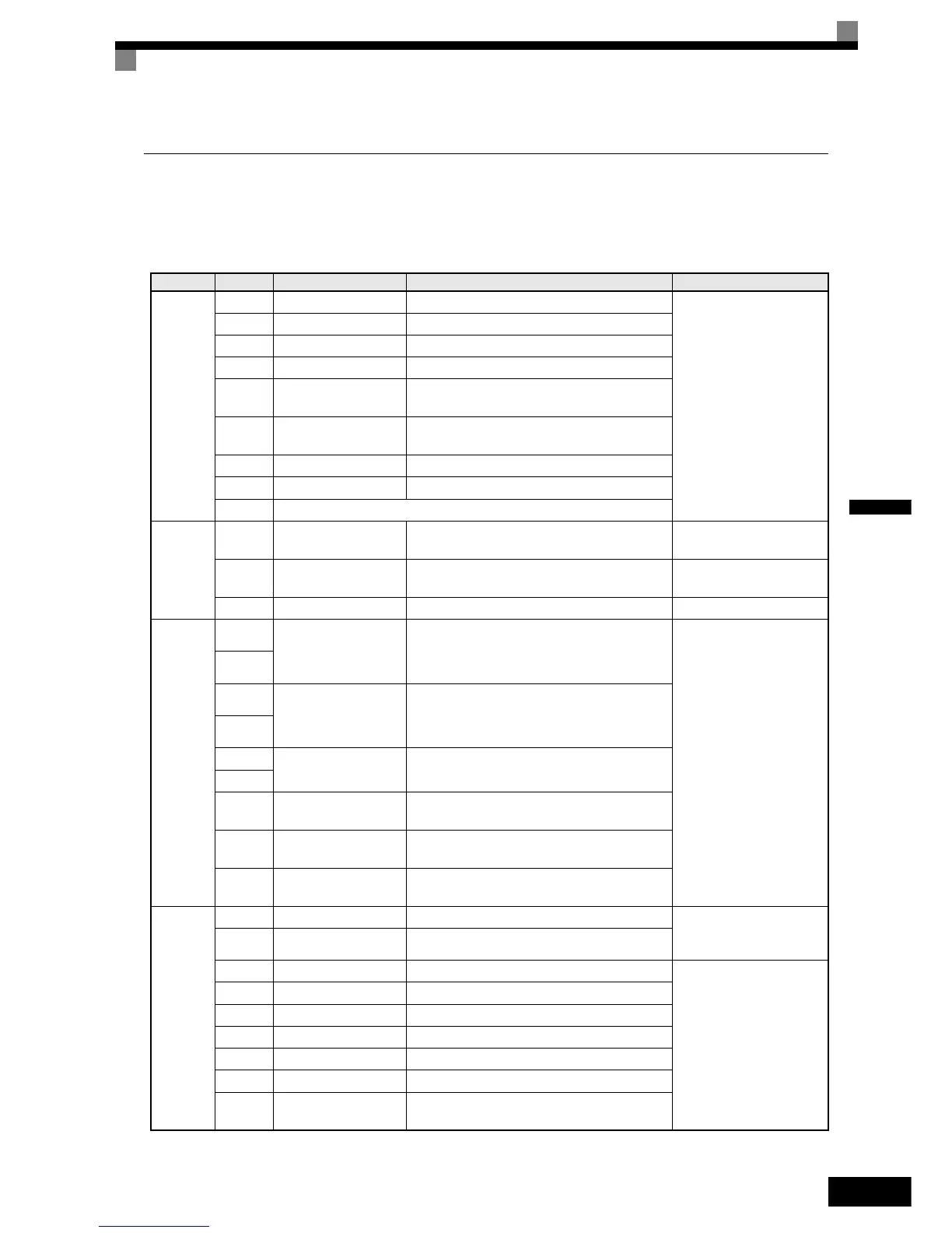
The functions of the control circuit terminals are shown in Table 2.10. Use the appropriate terminals for the
correct purposes.
Table 2.10 Control Circuit Terminals with default settings
Type
Terminal Signal Function Description Signal Level
Digital
input
signals
S1 Forward run/stop Forward run at "closed", stop at "open"
Opto-coupler isolation
Input +24VDC 8mA
S2 Reverse run/stop Reverse run at "closed", stop at "open"
S3 External Fault Factory setting: Nominal speed at "closed" <2>
S4 Fault Reset Factory setting: fault reset at "closed" <2>
S5
Multi-function input
selection 1
Factory setting: Multi-step speed ref.1 at
"closed" <2>
S6
Multi-function input
selection 2
Factory setting: Multi-step speed ref.2 at
"closed" <2>
S7 JOG Reference Factory setting: JOG Reference at "closed" <2>
S8 Hardware baseblock baseblock release at "closed", effective at "open"
SC Sequence control input common terminal
Analog
input
signals
+V
+15V Power supply
output
For analog reference +15V power supply +15V
A1
Multi-function analog
input
0 to 10V/100%
Factory setting: Master freq.ref.
0 to10V
(Input impedance 20KΩ)
AC Analog common 0V −
Sequence
output
signals
M1
Multi-function contact
output 1 (NO contact)
Factory setting: Brake Command
Dry contact contact
capacity 250V AC 1A,
30V DC 1A
M2
M3
Multi-function contact
output 2 (NO contact)
Factory setting: Contactor Control
M4
M5
Multi-function contact
output 3 (NO contact)
Factory setting: During Inverter Ready
M6
MA
Fault output
(NO contact)
Fault at "closed"between terminals MA and MC
MB
Fault output
(NC contact)
Fault at "open"between terminals MB and MC
MC
Relay contact output
common
−
PG pulse
input
Power +12V/+5V PG power supply 12V/5V can be selected +12V: 200mA max
+5V: 200mA max
Impossible to use both
IG 0V PG power supply GND
A(+) + A phase positive pulse input
PG signal input
RS-422 level
A(-) - A phase negative pulse input
B(+) + B phase positive pulse input
B(-) - B phase negative pulse input
Z(+) + Z phase positive pulse input
Z(-) - Z phase negative pulse input
IG
PG pulse input com-
mon
0 V
http://nicontrols.com