2-22
* 1. Do not use this power supply for supplying any external equipment.
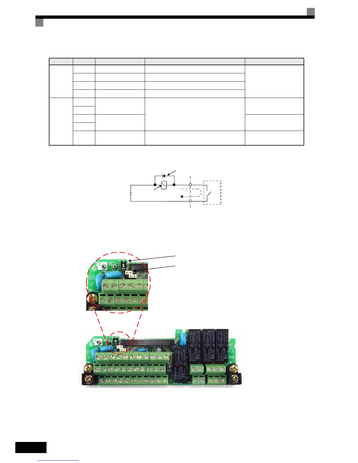
* 2. When driving a reactive load, such as a relay coil with DC power supply, always insert a flywheel diode as shown in Fig 2.12.
Fig 2.12 Flywheel Diode Connection
Shunt Connector CN5 and DIP Switch S1
The shunt connector CN5 and DIP switch S1 are described in this section.
Fig 2.13 Shunt Connector CN5 and DIP Switch S1
PG output
ratio
DA+ + A phase positive pulse monitor
PG output ratio
RS-422 level
DA- - A phase negative pulse monitor
DB+ + B phase positive pulse monitor
DB- - B phase negative pulse monitor
RS-422/
485
MEMO-
BUS
Commu-
nication
R+
MEMOBUS
communication input
When using two RS-485 wires, short-circuit
between R+ and S+, R- and S-
Differential input PHC
isolation
R-
S+
MEMOBUS
communication output
Differential input PHC
isolation
S-
IG
Shielded wire for
communication
− −
Table 2.10 Control Circuit Terminals with default settings (Continued)
Type
Terminal Signal Function Description Signal Level
External power:
30 VDC max.
Coil
Flywheel diode
1 A max.
The rating of the flywheel diode
must be at least as high as the
circuit voltage.
Terminating registance
(Default: OFF)
CN5 setting
(Default: NPN setting)
http://nicontrols.com