Wiring Control Circuit Terminals
2-19
2
Wiring Control Circuit Terminals
Wire Sizes
For remote operation using analog signals, keep the control line length between the Analog Operator or oper-
ation signals and the Inverter to 30 m or less, and separate the lines from main power lines or other control cir-
cuits to reduce induction from peripheral devices.
When setting frequencies from an external frequency source (and not from a Digital Operator/Monitor), used
shielded twisted-pair wires and ground the shield for the largest area of contact between shield and ground.
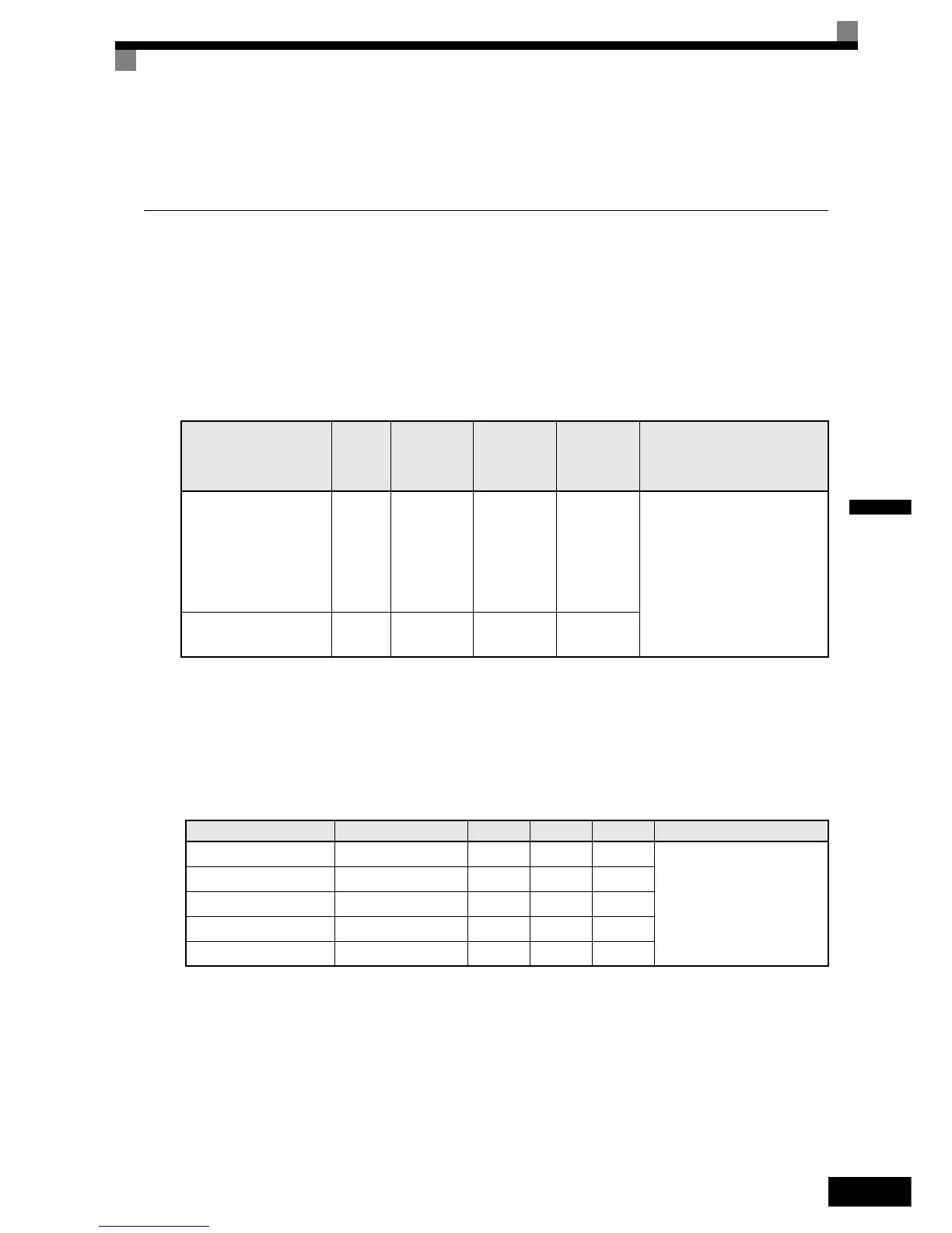
The terminal numbers and the appropriate wire sizes are shown in Table 2.8.
* 1. Use shielded twisted-pair cables to input an external frequency reference.
*2.Refer to Table 2.3 for suitable lug sizes for the wires.
* 3. We recommend using straight solderless terminal on signal lines to simplify wiring and improve reliability.
Straight Solderless Terminals for Signal Lines
Models and sizes of straight solderless terminal are shown in the following table.
Table 2.8 Terminal Numbers and Wire Sizes (Same for all Models)
Terminals
Te r m i -
nal
Screws
Tightening
Tor q u e
(N•m)
Possible
Wire Sizes
mm
2
(AWG)
Recom-
mended
Wire Size
mm
2
(AWG)
Wire Type
R+, R-, S+, S-IG, A+, A-,
B+, B-, Z+, Z-, PG+, PG-,
DA+, DA-, DB+, DB-,
AC, SC, A1, +V, S1, S2,
S3, S4, S5, S6, S7, BB,
MA, MB, MC, M1, M2,
M3, M4, M5, M6
Phoenix
type
0.5 to 0.6
Single wire
*3:
0.14 to 2.5
Stranded
wire:
0.14 to 1.5
(26 to 14)
0.75
(18)
• Shielded, twisted-pair wire*1
• Shielded, polyethylene-cov-
ered, vinyl sheath cable
(KPEV-S by Hitachi Electrical
Wire or equivalent)
E (G) M3.5 0.8 to 1.0
0.5 to 2
*2
(20 to 14)
1.25
(12)
Table 2.9 Straight Solderless Terminal Sizes
Wire Size mm
2
(AWG)
Model d1 d2 L Manufacturer
0.25 (24) AI 0.25 - 8YE 0.8 2 12.5
Phoenix Contact
0.5 (20) AI 0.5 - 8WH 1.1 2.5 14
0.75 (18) AI 0.75 - 8GY 1.3 2.8 14
1.25 (16) AI 1.5 - 8BK 1.8 3.4 14
2 (14) AI 2.5 - 8BU 2.3 4.2 14
http://nicontrols.com