Wiring Control Circuit Terminals
2-25
2
Control Circuit Terminal Connections
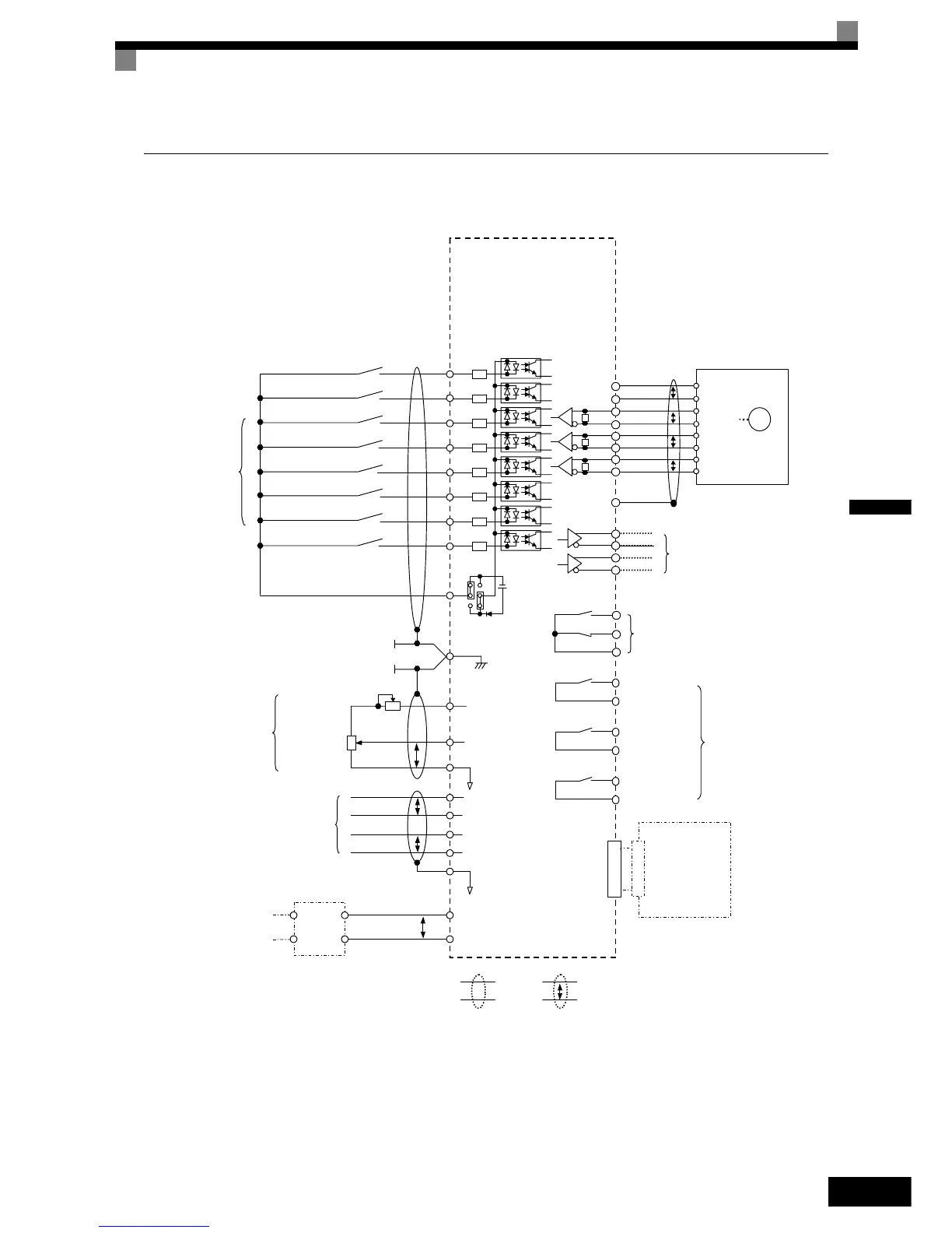
Connections to Inverter control circuit terminals are shown in Fig 2.15.
Fig 2.15 Control Circuit Terminal Connections
Note:
1.Main circuit terminals are indicatied with double circles and
control circuit terminals are indicatied with a single circles
2.The output current capacity of the +V terminal is 20mA
3.Sequence input signal S1 to S7 and BB are labelled for sequence
connections for no-voltage contacts or NPN transistors as the
default setting .
4. The master frequency reference is set to a voltage input refer-
ence as the default setting .
M B
Fault contact Output
250VAC 1A or less
30VDC 1A or less
Multi-fanction
contact Inputs
(Factory setting)
External frequency
reference
PG-
E(G)
PG+
Multi-fanction Contact Output
250VAC 1A or less
30VDC 1A or less
Brake Command
(Factory setting)
Contactor Control
(Factory setting)
Inverter Ready
(Factory setting)
2CN
Communication
and
Control Cards
(For Option)
DC/DC
Converter
For option
Output Voltage
For Contorl power supply
Input Voltage
48/96VDC
For Battery
Forward run/stop
Reverse run/stop
External Fault
Hardware baseblock
Fault Reset
Multi f-step speed setting 1
JOG reference
S1
S2
S3
S4
S5
S6
S7
BB
SC
CN5 (NPN setting)
+24V 8mA
IP24V (24V)
E(G)
3
2
1
0 to 10V
2KΩ
P
2KΩ
+V
A1
AC
Frequency setting
adjustment
Master speed
reference 0 to 10V
0V
Frequency setting
power +15V 20mA
Frequency setter
M A
M C
M 1
M 2
M 3
M 4
M 5
M 6
P0
N0
P
A Pulse
B Pulse
Pulse Monitor Output
RS-422 Level
(30m or less wiring)
PG
Shielded
wires
Twisted-pair
wires
P
P
A(+)
A(-)
B(-)
B(+)
Z(+)
Z(-)
P
DA(+)
DA(-)
DB(+)
DB(-)
P
P
P
MOMOBUS
communication
RS-485/422
IG
Multi f-step speed setting 2
R+
R-
S-
S+
http://nicontrols.com