1-14
Inverters of 22 kW or More
For inverters with an output of 22 kW or more, remove the terminal cover and then use the following proce-
dures to remove the Digital Operator/Monitor and main cover.
Removing the Digital Operator/Monitor
Use the same procedure as for Inverters with an output of 18.5 kW or less.
Removing the Front Cover
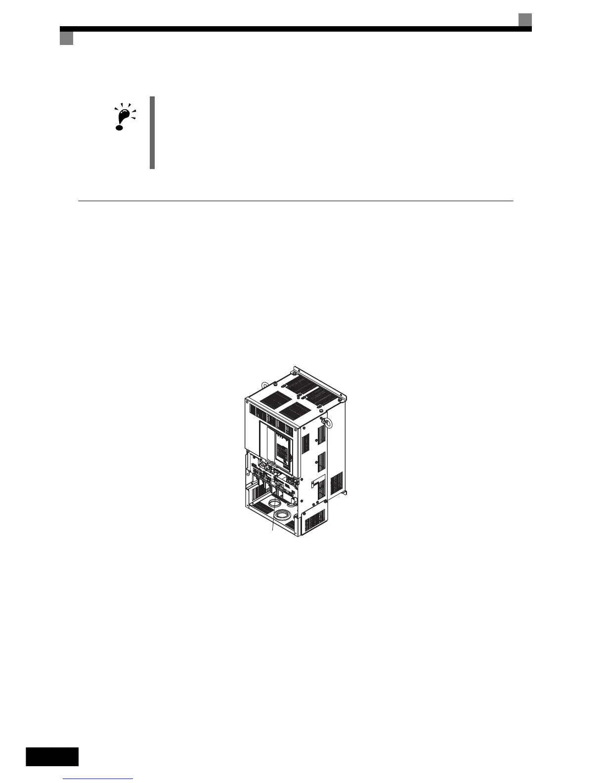
Lift up at the location label 1 at the top of the control circuit terminal card in the direction of arrow 2.
Fig 1.16 Removing the Front Cover (Model CIMR-L7C4022 Shown Above)
Attaching the Front Cover
After completing required work, such as mounting an optional card or setting the terminal card, attach the
front cover by reversing the procedure to remove it.
1. Confirm that the Digital Operator/Monitor is not mounted on the front cover. Contact faults can occur if
the cover is attached while the Digital Operator/Monitor is mounted to it.
2. Insert the tab on the top of the front cover into the slot on the Inverter and press in on the cover until it
clicks into place on the Inverter.
Attaching the Digital Operator/Monitor
Use the same procedure as for Inverters with an output of 18.5 kW or less.
IMPORTANT
1. Do not remove or attach the Digital Operator/Monitor or mount or remove the front cover using methods
other than those described above, otherwise the Inverter may break or malfunction due to imperfect con-
tact.
2. Never attach the front cover to the Inverter with the Digital Operator/Monitor attached to the front cover.
Imperfect contact can result.
Always attach the front cover to the Inverter by itself first, and then attach the Digital Operator/Monitor to
the front cover.
1
2
http://nicontrols.com