2-16
Cable Length between Inverter and Motor
The cable between the Inverter and motor is 30 m max.
Ground Wiring
Observe the following precautions when wiring the ground line.
• Always use the ground terminal of the 200 V Inverter with a ground resistance of less than 100 Ω and that
of the 400 V Inverter with a ground resistance of less than 10 Ω.
• Do not share the ground wire with other devices, such as welding machines or power tools.
• Always use a ground wire that complies with technical standards on electrical equipment and minimize the
length of the ground wire.
Leakage current flows through the Inverter. Therefore, if the distance between the ground electrode and the
ground terminal is too long, potential on the ground terminal of the Inverter will become unstable.
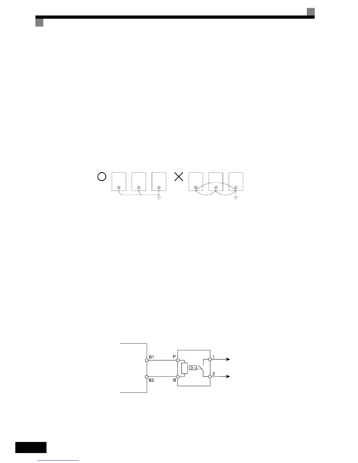
• When using more than one Inverter, be careful not to loop the ground wire.
Fig 2.6 Ground Wiring
Connecting a Braking Resistor and Braking Unit (CDBR)
Connect a Braking Resistor Unit and Braking Unit to the Inverter as shown in the Fig 2.7.
Connecting a Braking Resistor and Braking Unit (CDBR)
Connect a Braking Resistor and Braking Unit to the Inverter like shown in the Fig 2.7.
The example shows a braking resistor with integrated thermal overload switch. To prevent the braking unit/
braking resistor from overheating, design the control circuit to turn OFF the power supply using the thermal
overload relay contacts of the units as shown in
Fig 2.7.
200 V and 400 V Class Inverters with 3.7 to 18.5 kW Output Capacity
OK
NO
Inverter
Braking Resistor Unit
Thermal overload
relay contact
http://nicontrols.com