Protective and Diagnostic Functions
6-9
6
Alarm Detection
Alarms are Inverter protection function that do not operate the fault contact output. The system will automati-
cally return to its original status when the cause of the alarm has been removed.
During an alarm condition, the Digital Operator/Monitor display flashes and an alarm ouput is generated at the
multi-function outputs (H2-01 to H2-03) if programmed
When an alarm occurs, take appropriate countermeasures according to the table below.
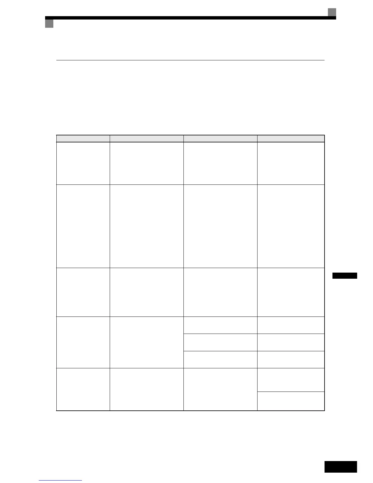
Table 6.2 Alarm Detection
Display Meaning Probable causes Corrective Actions
EF
External Fault
(flashing)
Forward/Reverse Run Com-
mands Input Together
Both the forward and the reverse
run commands are input simulta-
neously for 500ms or more. This
alarm stops the motor.
The external forward and reverse
command were input simulta-
neously.
Check external sequence
logic, so only one input is
received at a time.
UV
DC Bus Undervolt
(flashing)
DC Bus Undervoltage
The following conditions
occurred
• The DC bus voltage was below
the Undervoltage Detection
Level Setting (L2-05).
• The MC of the inrush current
prevention circuit opened.
• The control power supply volt-
age when below the CUV level.
UV Alarm is only detected when
the drive is in a stopped condition
For the probable causes please
have a look at UV1, UV2 and
UV3 in table 7.1.
For the corrective actions
please have a look at UV1,
UV2 and UV3 in table 7.1
OV
DC Bus Overvolt
(flashing)
DC Bus Overvoltage
The DC bus voltage exceeded the
overvoltage detection level.
200 V class: 410 VDC
400 V class: 820 VDC
OV Alarm is only detected when
the drive is in a stopped condition
The power supply voltage is too
high.
Check the power supply and
decrease the voltage to meet
the Inverter’s specifications
OH
Heatsnk Overtmp
(flashing)
Heatsink Overheat
The temperature of the Inverter's
cooling fin exceeded the tempera-
ture programmed in L8-02.
Enabled when L8-03 = 3
The ambient temperature is too
high.
Check for dirt build-up on the
fans or heatsink.
There is a heat source nearby.
Reduce the ambient tempera-
ture around the Inverter
The Inverter cooling fan(s) has
stopped.
Replace the cooling fan(s).
OH2
Over Heat 2
(flashing)
Overheat Alarm
An OH2 alarm signal is input
from a multi-function digital
input terminal (S3 to S7) that is
programmed to OH2 Alarm Sig-
nal Input (H1- = B)
An external overheat condition
exists that was connected to one
of the multi-function input termi-
nals S3 to S7.
Check the external overheat
signal connected to the speci-
fied digital input.
Verify the parameter settings
in H1-
http://nicontrols.com