5-54
Digital Operator/Monitor Functions
Setting Digital Operator/Monitor Functions
Related Parameters
Monitor Selection (o1-01)
Using parameter o1-01 the third monitor item that is displayed in drive mode can be selected.
Monitor Display when the Power Supply is Turned ON (o1-02)
Using parameter o1-02 the monitor item (U1-) that is to be displayed on the Digital Operator/Monitor
when the power supply is turned ON can be selected.
Changing Frequency Reference and Display Units (o1-03)
Set the Digital Operator/Monitor frequency reference and display units using parameter o1-03. The setting in
o1-03 will affect the display units of the following monitor items:
• U1-01 (Frequency Reference)
• U1-02 (Output Frequency)
• U1-05 (Motor Speed)
• U1-20 (Output Frequency after Soft Start)
• d1-01 to d1-17 (Frequency references)
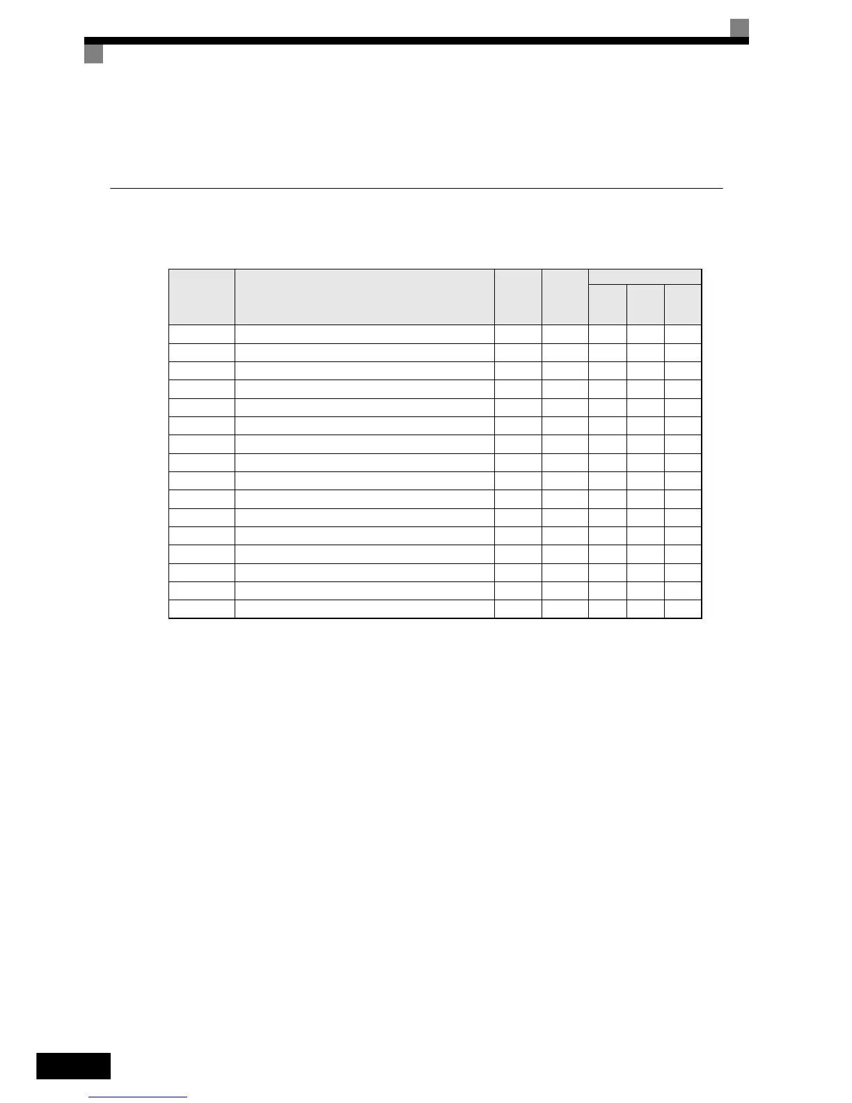
Parameter
No.
Name
Factory
Setting
Change
during
Opera-
tion
Control Methods
V/f
Open
Loop
Vector
Closed
Loop
Vector
o1-01 Monitor selection 6 Yes A A A
o1-02 Monitor selection after power up 1 Yes A A A
o1-03 Frequency units of reference setting and monitor 0 No A A A
o1-04 Setting unit for frequency reference related parameters 0 No No No A
o1-05 LCD Display contrast 3 Yes A A A
o2-02 STOP key during control circuit terminal operation 0 No A A A
o2-03 Inveter kVA selection 0 No A A A
o2-04 User parameter initial value 0 No A A A
o2-05 Frequency reference setting method selection 0 No A A A
o2-06 Operation selection when digital operator is disconnected 0 No A A A
o2-07 Cumulative operation time setting 0 No A A A
o2-08 Cumulative operation time selection 0 No A A A
o2-09 Initialize Mode 0 No A A A
o2-10 Fan operation time setting 0 No A A A
o2-12 Fault trace initialize 0 No A A A
o2-13 “Number of Travels” monitor initialize 0 No A A A
http://nicontrols.com