Connection Diagram
2-3
2
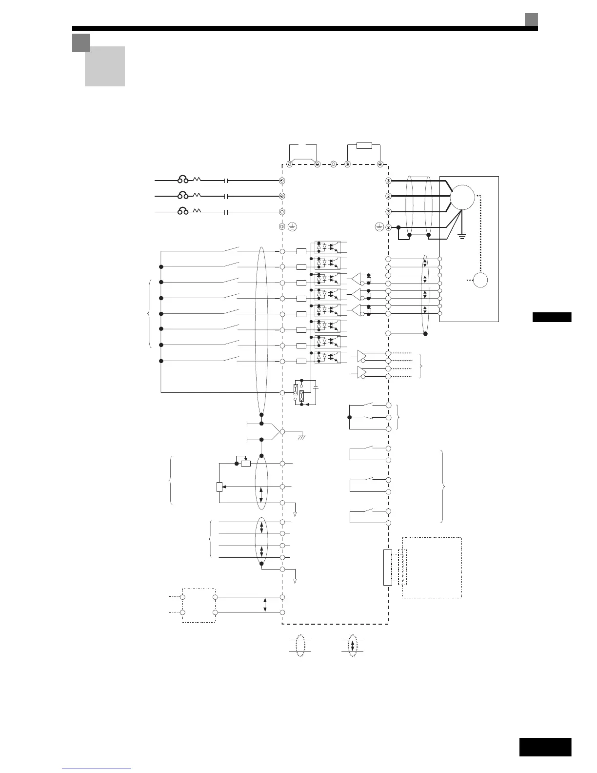
Connection Diagram
The connection diagram of the Inverter is shown in Fig 2.2.
When using the Digital Operator/Monitor, the motor can be operated by wiring only the main circuits.
Fig 2.2 Connection Diagram (Model CIMR-L7C43P7 Shown Above)
Note:
1.Main circuit terminals are indicatied with double circles and
control circuit terminals are indicatied with a single circles
2.The output current capacity of the +V terminal is 20mA
3.Sequence input signal S1 to S7 and BB are labelled for sequence
connections for no-voltage contacts or NPN transistors as the
default setting.
4.The master frequency reference is set to a voltage input reference
as the default setting.
B1
B2
(-)
IM/PM
PG-
Moter
E(G)
PG+
2CN
UX
Hardware baseblock
Fault Reset
Multi f-step speed setting 1
JOG reference
S1
S2
S3
S4
S5
S6
S7
BB
SC
CN5 (NPN setting)
+24V
8mA
IP24V (24V)
E(G)
3
2
1
0 to 10V
2KΩ
P
2KΩ
+V
A1
AC
0V
Frequency setter
U/T1
V/T2
W/T3
M 1
M 2
M 3
M 4
M 5
M 6
P0
N0
P
A Pulse
B Pulse
PG
P
P
A(+)
A(-)
B(-)
B(+)
Z(+)
Z(-)
P
DA(+)
DA(-)
DB(+)
DB(-)
P
P
P
IG
Multi f-step speed setting 2
R+
R-
S-
S+
T
S
R
MCCB
3-phase power
380 to 480V
50/60Hz
DC reactor to
improve input
power factor
(Optionnal)
Braking Resistor
unit (optional)
Short -circuit
Bar
Magnetic
Contactor
Forward run/stop
Reverse run/stop
External Fault
Multi-fanction
contact Inputs
(Factory setting)
Frequency setting
adjustment
External frequency
reference
MOMOBUS
communication
RS-485/422
Input Voltage
48/96VDC
For Battery
DC/DC
Converter
For option
Output Voltage
For Contorl power supply
Shielded
wires
Twisted-pair
wires
Frequency setting
power +15V 20mA
Master speed
reference 0 to 10V
(+1)
(+2)
L1(R)
L2(S)
L3(T)
Pulse Monitor Output
RS-422 Level
(30m or less wiring)
M A
M B
M C
Fault contact Output
250VAC 1A or less
30VDC 1A or less
Brake Command
(Factory setting)
Contactor Control
(Factory setting)
Inverter Ready
(Factory setting)
Multi-fanction Contact
Output
250VAC 1A or less
30VDC 1A or less
Communication
and
Control Cards
(For Option)
http://nicontrols.com