4-58
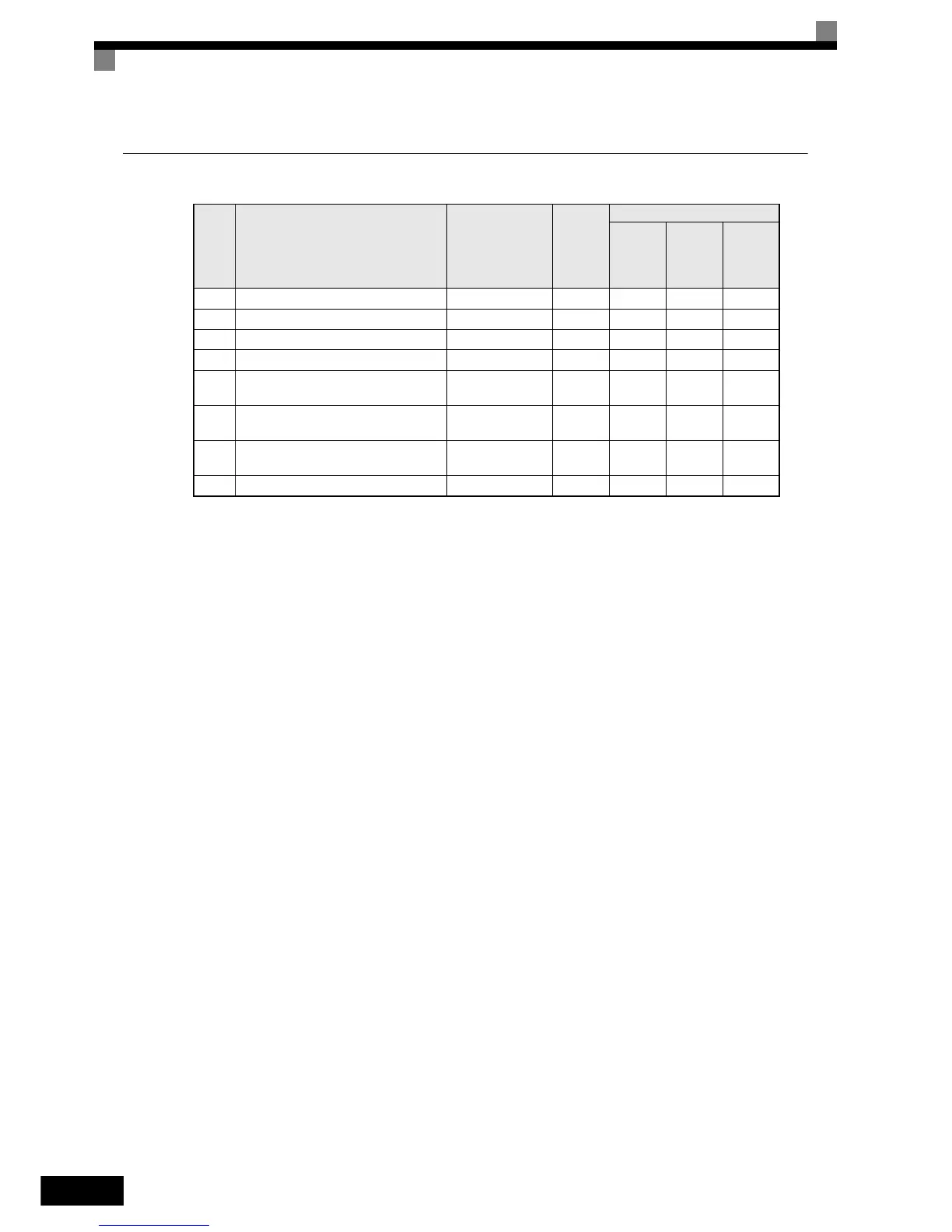
Factory Settings that Change with the Control Method (A1-02)
* 1. The settings are 0.05 (Closed Loop Vector) / 2.00 (Open Loop vector) for inverters of 55kW or larger.
* 2. Settings value as shown in the following tables depending on the Inverter capacity and E1-03.
* 3. The settings shown are for 200 V class Inverters. The values will double for 400 V class Inverters.
Param-
eter
Num-
ber
Name Setting Range Unit
Factory Setting
V/f Con-
trol
A1-02=0
Open
Loop
Vector
A1-02=2
Closed
Loop
Vector
A1-02=3
C3-01 Slip compensation gain 0.0 to 2.5 - 1.0 1.0 1.0
C3-02 Slip compensation delay time 0 to 10000 - 2000 200 0
C4-02 Torque compensation delay time constant 0 to 10000 - 200 50 0
E1-07 Mid. output frequency voltage 0.0 to 120.0 0.1 Hz 3.0 3.0 0
E1-08
Mid. output frequency voltage (VB)
*2
0.0 to 255.0
(0.0 to 510.0)
0.1 V
15.0
*2*3
11.0 0.0
E1-09 Min. output frequency (FMIN)
0.0 to 120.0
*4
0.1 Hz
1.5
*2
0.5 0.0
E1-10
Min. output frequency voltage (VMIN)
*2
0.0 to 255.0
(0.0 to 510.0)
0.1 V
9.0
*2*3
2.0 0.0
S1-04 DC injection braking time at stop 0.00 to 10.00 0.01 sec 0.50 0.30 0.00
http://nicontrols.com

 Loading...


