Acceleration and Deceleration Characteristics
5-21
5
Stall Prevention During Acceleration
The Stall Prevention During Acceleration function prevents the motor from stalling if the load is too heavy.
If L3-01 is set to 1 (enabled) and the Inverter output current reaches 85 % of the set value in L3-02, the accel-
eration rate will begin to slow down. When L3-02 is exceeded, the acceleration will stop.
If L3-01 is set to 2 (optimum adjustment), the motor accelerates so that the current is held at the level set in
L3-02. With this setting, the acceleration time setting is ignored.
Related Parameters
Time Chart
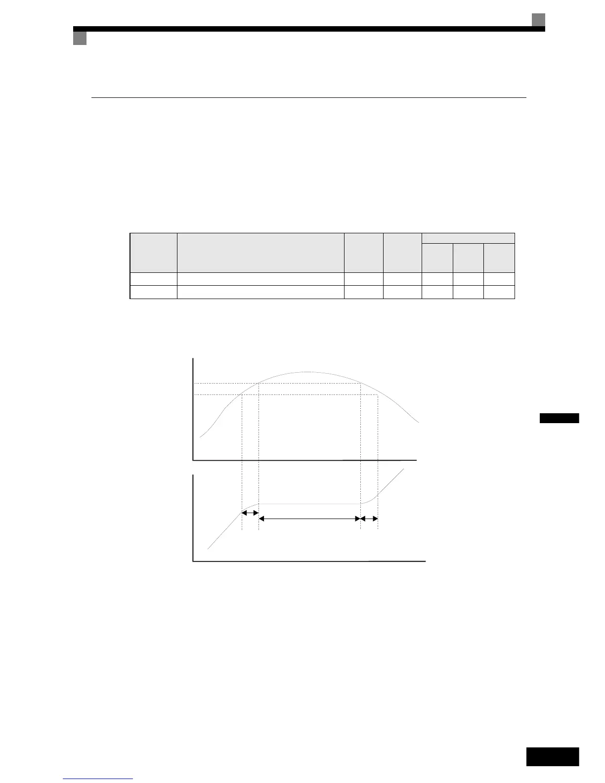
The following figure shows the frequency characteristics when L3-01 is set to 1.
Fig 5.9 Time Chart for Stall Prevention During Acceleration
Setting Precautions
• Set the parameters as a percentage taking the inverter rated current to be 100%.
• Do not increase the stall prevention level unnecessarily. An extremely high setting can reduce the inverter
lifetime. Also do not disable the function.
• If the motor stalls with the factory settings check the V/f pattern settings (E1-) and the motor setup
(E2-).
• If the stall level has to be increased very much to get the elevator running, consider to use a one size bigger
inverter.
Parameter
No.
Name
Factory
Setting
Change
during
Operation
Control Methods
V/f
Open
Loop
Vector
Closed
Loop
Vector
L3-01 Stall prevention selection during acceleration 1 No A A No
L3-02 Stall prevention level during acceleration 150%* No A A No
Output current
Stall level during
acceleration
Time
Time
Output frequency
* 1. The acceleration rate is lowered.
* 2. The acceleration is stopped to reduce the output current.
*1.
*2.
L3-02
85% of L3-02
http://nicontrols.com