5-52
Setting the V/f Pattern 1
Using the E1- parameters the Inverter input voltage and the V/f pattern can be set as needed. It is not rec-
ommended to change the settings when the motor is used in Open Loop or Closed Loop vector control mode.
Related Parameters
* 1. These are values for a 200 V Class Inverter. Values for a 400 V Class Inverter are double.
* 2. The factory setting will change when the control method is changed. (Open Loop Vector control factory settings are given.)
* 3. The contents of parameters E1-11 and E1-12 are ignored when set to 0.00.
* 4. E1-13 is set to the same value as E1-05 by autotuning.
Setting Inverter Input Voltage (E1-01)
Set the Inverter input voltage correctly in E1-01 so that it matches the power supply voltage.
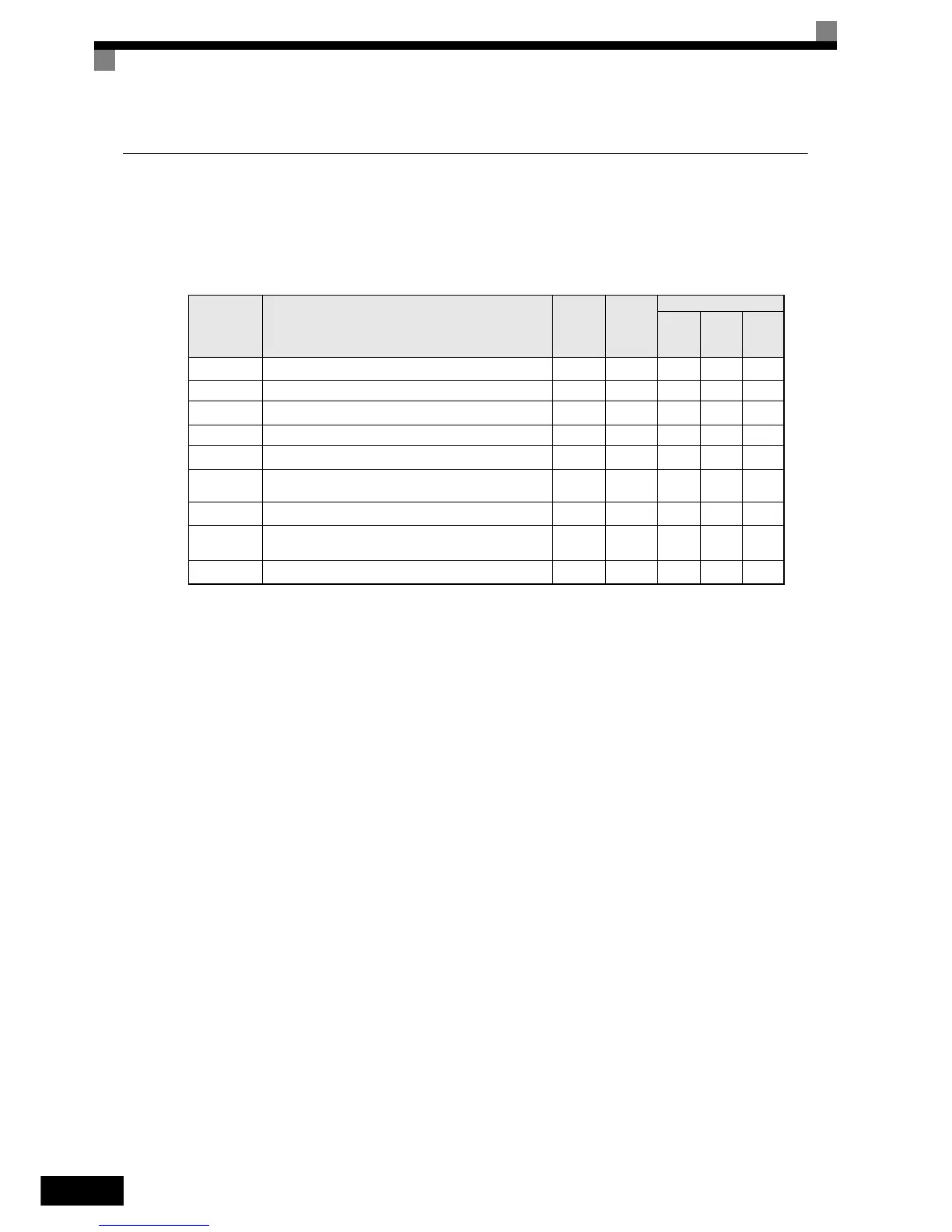
Parameter
No.
Name
Factory
Setting
Change
during
Opera-
tion
Control Methods
V/f
Open
Loop
Vector
Closed
Loop
Vector
E1-01 Input voltage setting
200 V
*1
No QQQ
E1-04 Max. output frequency (FMAX) 60.0 Hz No Q Q Q
E1-05 Max. voltage (VMAX)
200.0 V
*1
No QQQ
E1-06 Base frequency (FA) 60.0 Hz No Q Q Q
E1-07 Mid. output frequency (FB)
3.0 Hz
*2
No A A No
E1-08 Mid. output frequency voltage (VB)
15.0 V
*1*2
No Q Q No
E1-09 Min. output frequency (FMIN)
1.5 Hz
*2
No QQA
E1-10 Min. output frequency voltage (VMIN)
9.0 V
*1*2
No Q Q No
E1-13 Base voltage (VBASE)
0.0 V
*4
No A No No
http://nicontrols.com
 Loading...


