Battery Operation
5-65
5
Battery sequence
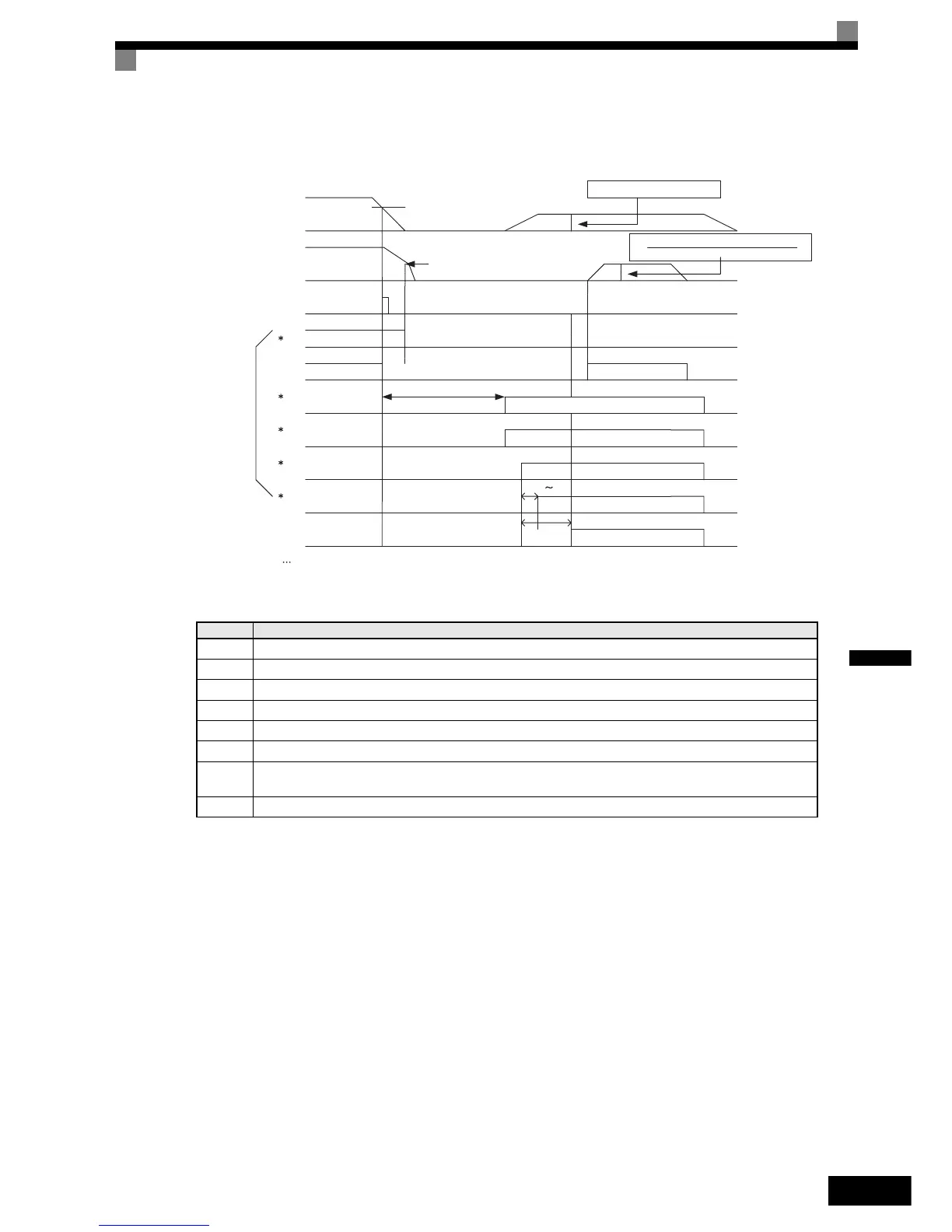
The following timing chart shows the sequence of battery operation.
(CAUTION)
1. Battery operation speed
The speed during the battery operation will be limited as the following fomula.
Speed during battery operation= (battery voltage x base speed ) / (300Vx2 )
When the 400V Class will be 600Vx2
2.Continuous operation is prohibited.
The cooling fan of inverter is stopped due to the low bus voltage.
Therefore the continuous operation of inverter is prohibited.
No. Description
1 When the bus voltage is blow the under voltage level, the inverter detects the under voltage(UV) fault.
2 Turn off the RUN command.
3 C and D contactors must be turned off and turn on the motor mechanical brake.
4 Need the appox. 5sec to start battery operation.
5 The multi-function digital input which is assigned with the battery operation command(E) must be turned ON.
6 A’ contactor must be turned ON after passing 0.2~0.3 sec when A and B main contactors are turned ON.
7
The RUN commands turns ON after inverter ready status set.
The battery operation time must be within 1min.
8 E, A, B and A’ contactors must be turned OFF after RUN command OFF.
Approx. 5sec
UV det level
Fault
Vpn
Motor speed
Brake
Coasting
C,D input contactor OFF
Battery operation
ON
Battery
operation command E
ON
Main Circuit
contactor
A,B
A’contactor
Inverter ready
battery voltage x base speed
300(600 *1 )x2
Approx. 1min
Battery voltage
0.2 0.3sec
Approx.
1sec
* exteranal operation signal
The power source of
these contactors must
keep supplying even if
power loss.
*1: 400VClass
using 600V
http://nicontrols.com