6-4
OH
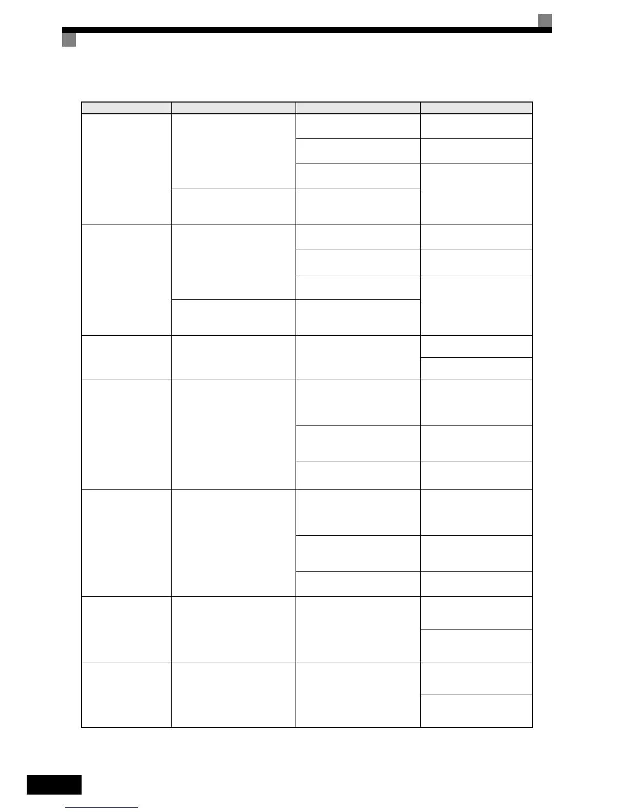
Heatsink Overtemp
Heatsink Overheat
The temperature of the Inverter's
cooling fin exceeded the setting in
L8-02 and L8-03 = 0 to 2.
The ambient temperature is too
high.
Check for dirt build-up on the
fans or heatsink.
There is a heat source nearby.
Reduce the ambient tempera-
ture around the drive.
The Inverter's cooling fan(s)
stopped.
Replace the cooling fan(s).
Inverter's Cooling Fan Stopped
The Inverter's internal cooling fan
has stopped
(18.5 kW and larger).
OH1
Heatsink Max Temp
Heatsink Overheat
The temperature of the Inverter’s
heatsink exceeded 105 °C.
The ambient temperature is too
high.
Check for dirt build-up on the
fans or heatsink.
There is a heat source nearby.
Reduce the ambient tempera-
ture around the drive.
The Inverter’s cooling fan(s)
stopped.
Replace the cooling fan(s).
Inverter’s Cooling Fan Stopped
The Inverter’s internal cooling fan
has stopped
(18.5 kW and larger).
RR
DynBrk Transistr
Dynamic Braking Transistor
The built-in dynamic braking
transitor failed.
Defective or failed dynamic brak-
ing resistor caused braking tran-
sistor damage.
Cycle power to the Inverter.
Replace the Inverter.
OL1
Motor Overload
Motor Overload
Detected when L1-01 = 1 to 3 and
the Inverter’s output current
exceeded the motor overload
curve.
The overload curve is adjustable
using parameter E2-01 (Motor
Rated Current), L1-01(Motor Pro-
tection Selection) and L2-02
(Motor Protection Time Constant)
The load is too large. The acceler-
ation time, deceleration time or
cycle time are too short.
Recheck the cycle time and
the size of the load as well as
the accel/decel times
(C1-).
The voltage settings of the V/f
pattern is incorrect for the appli-
cation.
Check the V/f characteristics
(E1-).
The setting of Motor Rated Cur-
rent (E2-01) is incorrect.
Check the setting of Motor
Rated Current Setting (E2-01).
OL2
Inv Overload
Inverter Overload
The Inverter output current
exceeded the Inverter’s overload
curve.
The load is too large. The acceler-
ation time or deceleration times
are too short.
Recheck the cycle time and
the size of the load as well as
the accel/decel times
(C1-).
The voltage settings of the V/f
pattern is incorrect for the appli-
cation.
Check the V/f characteristics
(E1-).
The size of the Inverter is too
small.
Check the setting of Motor
Rated Current Setting (E2-01).
OL3
Cur Stuck 1
Cur Stuck 1
The Inverter’s output current (V/f
control) or the output torque (Vec-
tor Control) exceeded L6-02 for
longer then the time set in
L6-03 and L6-01 = 3 or 4.
Motor was overloaded.
Ensure the values in L6-02
and L6-03 are appropriate.
Check application/machine
status to eliminate fault.
OL4
Cur Stuck 2
Cur Stuck 2
The Inverter’s output current (V/f
control) or the output torque (Vec-
tor Control) exceeded L6-05 for
longer then the time set in
L6-06 and L6-04 = 3 or 4.
Motor was overloaded.
Ensure the values in L6-05
and L6-06 are appropriate.
Check application/machine
status to eliminate fault.
Table 6.1 Fault Detection (Continued)
Display Meaning Probable Causes Corrective Actions
http://nicontrols.com