Maintenance and Inspection
7-5
7
200 V and 400 V Class Inverters of 22 kW or More
The heatsink cooling fan is attached to the top of the heatsink inside the Inverter. The cooling fan(s) can be
replaced without removing the Inverter from the installation panel.
Removing the Cooling Fan
1. Always turn OFF the input power before removing and installing the heatsink cooling fan assembly.
2. Remove the terminal cover, Inverter cover, Digital Operator/Monitor, and front cover from the Inverter.
3. Remove the control PCB (if necessary) bracket to which the cards are mounted. Remove all cables con-
nected to the control PCB and remove the cooling fan power connectro fro mthe fan board positioned near
the top of the Inverter.
4. Remove the cooling fan power connectors from the gate drive board positioned at the back of the Inverter.
5. Remove the fan assembly screws and pull out the fan assembly from the Inverter.
6. Remove the cooling fan(s) from the fan assembly.
Mounting the Cooling Fan
After attaching the new cooling fan(s), reverse the above procedure to attach all of the components.
When attaching the cooling fan to the mounting bracket, be sure that the air flow direction faces the top of the
Inverter.
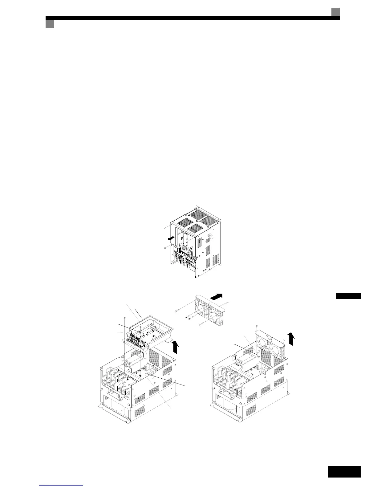
Fig 7.5 Cooling Fan Replacement (Inverters of 22 kW or More)
Control card
Control card
bracket
Gate driver
Connector
Fan Assembly
Air flow direction
http://nicontrols.com

 Loading...


