3-2
LED Monitor for JVOP-163
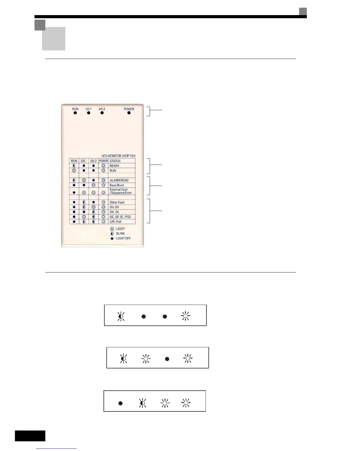
LED Monitor
Indicators the operation status by the combination of the LED displays (Lights up, Blink, and Off) at RUN,
DS1, and DS2.
The LED pattern is as follows at each mode.
Note: When a combination of LED pattern different from above table occurs, it is CPF00 or CPF01 Fault.
LED Display when the Power is ON
Normal operation: The figure below shows the LED display when the drive is ready and no FWD/REV
signal is acticve
Alarm: The figure below shows an example of the LED display when a minor fault occurs.
Refer to Chapter 6 and take appropriate countermeasures.
Fault: The figure below shows an example of the LED display when an OV or UV fault has
occured
Operation Mode Indicators
RUN: Lights up during inverter run, Off if the inverter is
stopped
DS1: Drive Status 1
DS2: Drive Status 2
The combination of the three LEDs Run, DS1 and DS2
indicates the drive status.
Drive Status Indications
Alarm Indications
Fault Indications
RUN DS1 DS2 POWER
RUN DS1 DS2 POWER
RUN DS1 DS2 POWER
http://nicontrols.com