4-32
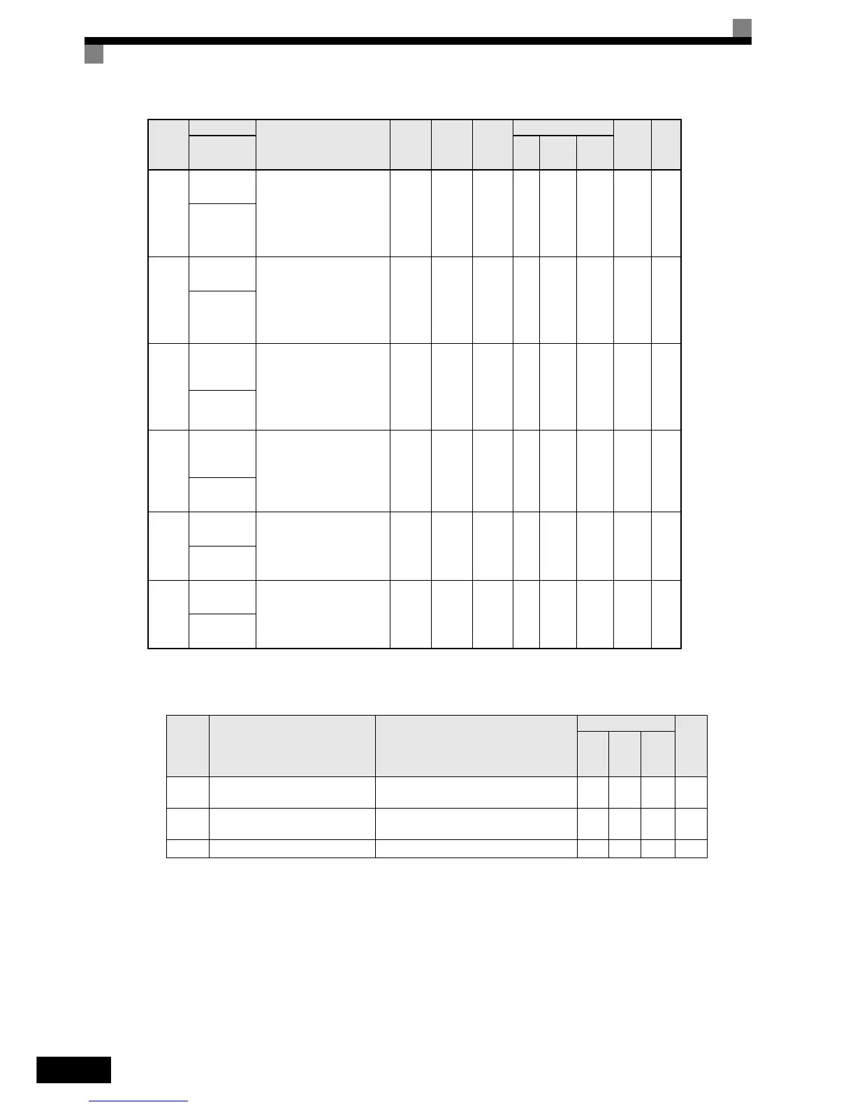
These parameters display when AI-14B is installed.
H3-05,H3-09 Settings
H3-10
Gain (AI-14
CH2)
Sets the input gain (level)
when terminal 14 is 10 V (20
mA).
Set according to the 100%
value for the function set for
H3-09.
0.0 to
1000.0
100.0% Yes A A A 419H 5-48
AI-14 CH2
Gain
H3-11
Bias (AI-14B
CH2)
Sets the input gain (level)
when terminal 14 is 0 V (4
mA).
Set according to the 100%
value for the function set for
H3-09.
-100.0
to
+100.0
0.0% Yes A A A 41AH 5-48
AI-14B CH2
Bias
H3-12
Analog input
filter time
constant
Sets primary delay filter time
constant in seconds for the
two analog input (A1 and AI-
14B CH1,2,3).
Effective for noise control
etc.
0.00 to
2.00
0.03
s
No A A A 41BH 5-48
Filter Avg
Time
H3-15
Terminal A1
function
selection
Sets the multi-function analog
input function for terimnal
A1.
0: Frequency Referemce
1: Torque compensation
0 or 1 0 No A A A 434H -
Terminal A1
Sel
H3-16
Gain (Termi-
nal A1)
Sets the frequency when 10 V
is input, as a percentage of the
maximum output frequency.
0.0 to
1000.0
100.0% Yes A A A 435H -
Terminal A1
Gain
H3-17
Bias (Termi-
nal A1)
Sets the frequency when 0 V
is input, as a percentage of the
maximum frequency.
-100.0
to
+100.0
0.0% Yes A A A 436H -
Terminal A1
Bias
Setting
Value
Function Contents (100%)
Control Methods
Page
V/f
Open
Loop
Vec-
torop
Closed
Loop
Vector
2
Auxiliary frequency reference (is used
as frequency reference 2)
Maximum output frequency (AI-14B use only) Yes Yes Yes 5-6
3
Auxiliary frequency reference (is used
as frequency reference 3)
Maximum output frequency (AI-14B use only) Yes Yes Yes 5-6
14 Torque compensation Motor’s rated torque (AI-14B use only) No No Yes -
Con-
stant
Number
Name
Description
Setting
Range
Factory
Setting
Change
during
Opera-
tion
Control Methods
MEMO
BUS
Regis-
ter
Page
Display
V/f
Open
Loop
Vector
Close
Loop
Vector
http://nicontrols.com