2-8 IM 04L20A01-01E
2.4 Optional Input/Output Terminal Wiring
General Precautions When Wiring the Input/Output Signal Wires
WARNING
• To prevent the possibility of electric shock when wiring, confirm that the power
supply source is turned OFF.
• If a voltage greater than or equal to 30 VAC/60 VDC is going to be applied to the
output terminals, use round crimp-on lugs with insulation covers (to prevent the
wires from coming loose) for connecting the signal wires on all output terminals. In
addition, use double insulated wires (withstand voltage of 2300 VAC or more) for
signal wires to which a voltage greater than or equal to 30 VAC/60 VDC is to be
applied and basic insulation wires (withstand voltage of 1350 VAC or more) for all
other signal wires. To prevent the possibility of electric shock, attach the terminal
cover after connecting the wires and keep your hands away from the terminals.
CAUTION
If a large pulling force is applied to the input/output signal wires connected to the
FX100, the terminal or signal wire may become damaged. To prevent this from
happening, fix all the wiring cords to the rear of the installation panel.
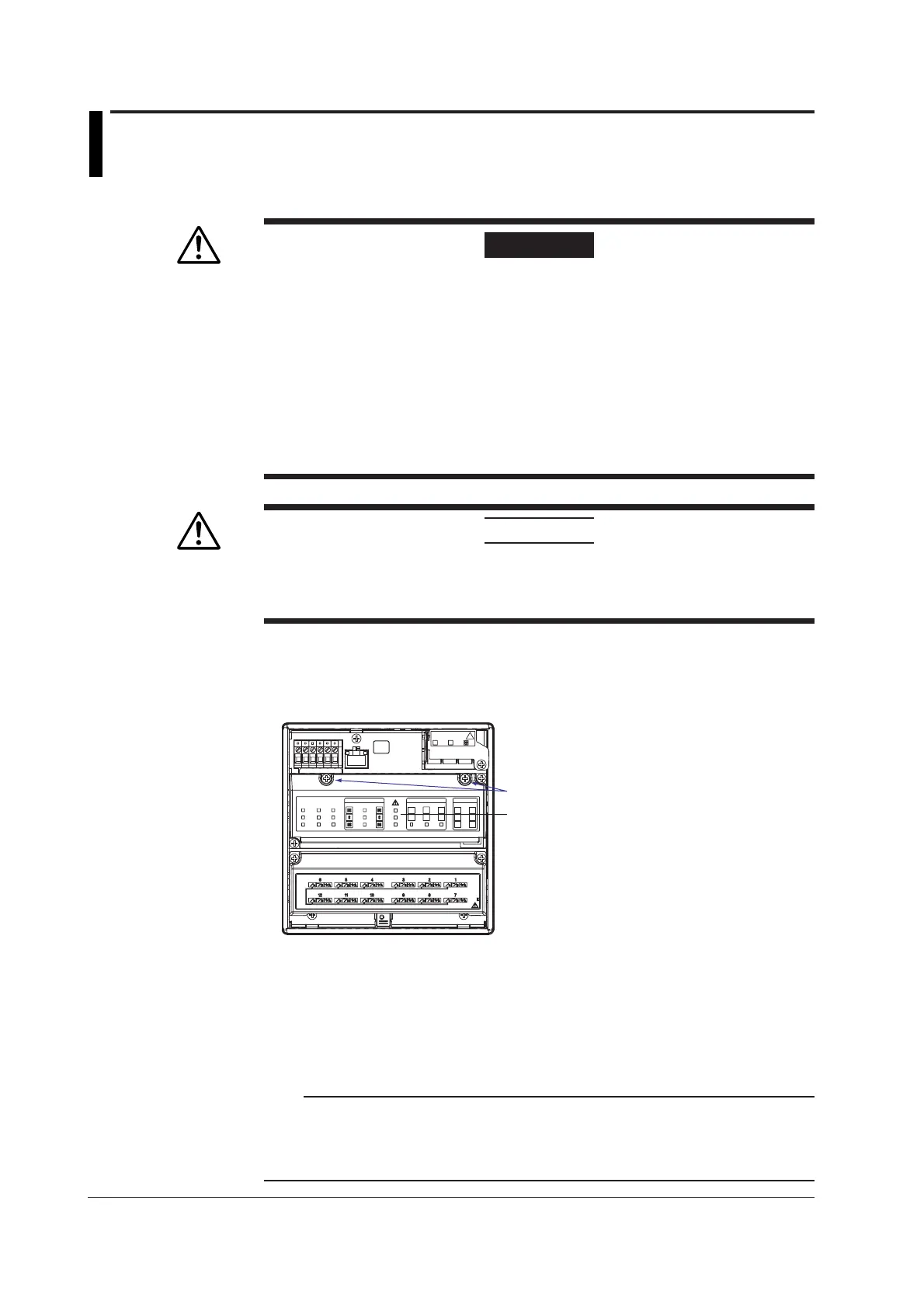
Arrangement of the Option Terminal Block
The option terminal block is arranged on the rear panel of the FX100 as shown in the
figure below.
Option terminal block
Terminal cover screws
The option terminal block is included when the following option codes are specified.
Alarm output relay (option code: /A1, /A2, /A3), FAIL/memory end output relay (option
code: /F1), remote control (option code: /R1), pulse measurement input (option code: /
PM1)
A terminal cover is screwed on the option terminal block. A label showing the
arrangement of the terminals is affixed to the cover.
Note
• The installation position of each terminal block is fixed and cannot be changed.
• For a description on the connection of communication interfaces such as the serial or
Ethernet interface, see the “
FX100 Communication Interface User’s Manual
” (IM04L20A01-
17E).

 Loading...


