2-9
IM 04L20A01-01E
Installation and Wiring
2
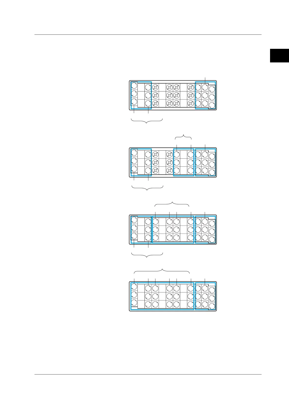
Terminal Arrangement on the Option Terminal Block
Terminals are arranged as shown in the figure below according to the options
installed. You can use only the terminals that correspond to the options you
purchased.
• When pulse input (/PM1) is not installed
02 01
FAIL/Memory end output (/F1)
7 4
1
2
58
6 3
C
C
NO
NC
C
NO
NC
C
NO
NC
C
NO
NC
FAIL
Memory end
Alarm output (/A1)
With /A1
With /A2
With /A3
Remote input (/R1)
FAIL/Memory end output (/F1)
7 4
1
2
58
6 3
C
C
NO
NC
C
NO
NC
FAIL
Memory end
Without alarm
output terminals
Remote input (/R1)
02 0104 03
FAIL/Memory end output (/F1)
7 4
1
2
58
6 3
C
C
NO
NC
C
NO
NC
C
NO
NC
C
NO
NC
C
NO
NC
C
NO
NC
FAIL
Memory end
Alarm output (/A2)
Remote input (/R1)
02 0104 0306 05
7 4
1
2
58
6 3
C
C
NO
NC
C
NO
NC
C
NO
NC
C
NO
NC
C
NO
NC
C
NO
NC
Alarm output (/A3)
Remote input (/R1)
NC (normally closed), C (common), NO (normally opened): Relay contact output terminal
1 to 8, C (common): Remote input terminal
The alarm output terminals 01 to 06 are indicated using [I01] to [I06] in the alarm output
settings.
The remote input terminals 1 to 8 are indicated using numbers 1 to 8 in the remote
output settings.
2.4 Optional Input/Output Terminal Wiring

 Loading...


