6-12 IM 04L20A01-01E
6.7 Displaying Waveforms in Separate Zones on
the Trend Screen
This section explains how to specify the waveform display zone of each channel.
Waveform Display Zone <Setting Mode>
Procedure
Opening the Setting Display
• Waveform display zone
MENU key (switch to setting mode) > #5 soft key (select [Display]) > #3 soft key
(select [Zone, Graph]) or #6 soft key (select [Math (Zone, Graph)])
If [Aux, Time Zone] > [Partial] is set to [Use], [Zone, Graph] in the menu appears as
[Zone, Graph, Partial], and the setting display shows the [Partial] entry box.
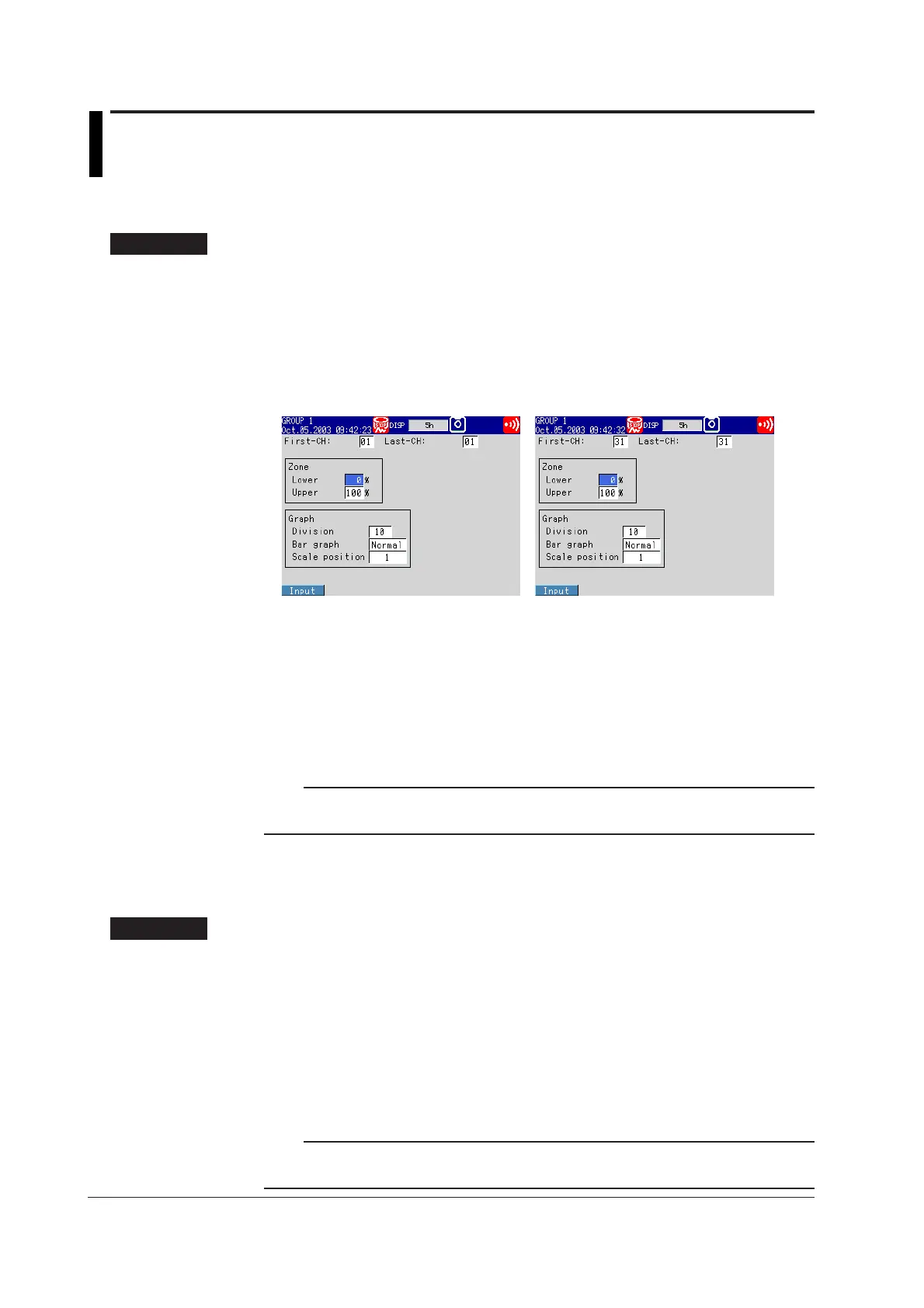
From the operation mode, use the above keys to open the following setting display.
For measurement channels For computation channels (
/M1, /PM1 option)
Setup Procedure
1. Use the arrow keys to move the cursor (blue) to the item box you wish to
change.
A soft key menu is displayed at the bottom of the display.
2. Press the soft key corresponding to the value you wish to select.
The box for the item you changed turns yellow, and the cursor moves to the next
item.
3. Repeat steps 1 and 2 to change the value of all the items you wish to change.
Note
The [Zone Lower/Upper] is set using the pop-up window that appears by pressing the [Input]
soft key.
4. Press the DISP/ENTER key to confirm the changes.
The boxes for the items you changed turn from yellow to white, and the cursor
returns to the first item box.
Setup Items
Setting Zone Lower/Upper
• First-CH/Last-CH
Set the target channel (common with the [Graph] setting).
Measurement channels: 01 to 12, computation channels: 31 to 42 (/M1, /PM1 option)
• Zone Lower/Upper
Set the zone for displaying the target channel. You can set [Zone Lower] and [Zone
Upper] as a position (%) when taking the maximum display width to be 0 to 100% in
the following range.
Zone Lower: 0 to 95%, Zone Upper: 5 to 100%
Note
• [Lower] must be a smaller value than [Upper].
• The width of the zone (upper limit − lower limit) must be greater than or equal to 5%.

 Loading...


