2-10
IM 04P03B01-01E
Explanation
Alarm Type
Symbol Name Notes
H ( ) High limit alarm
L ( ) Low limit alarm
h ( ) Difference high limit alarm Can be specified on channels set to delta computation.
l ( ) Difference low limit alarm Can be specified on channels set to delta computation.
Note
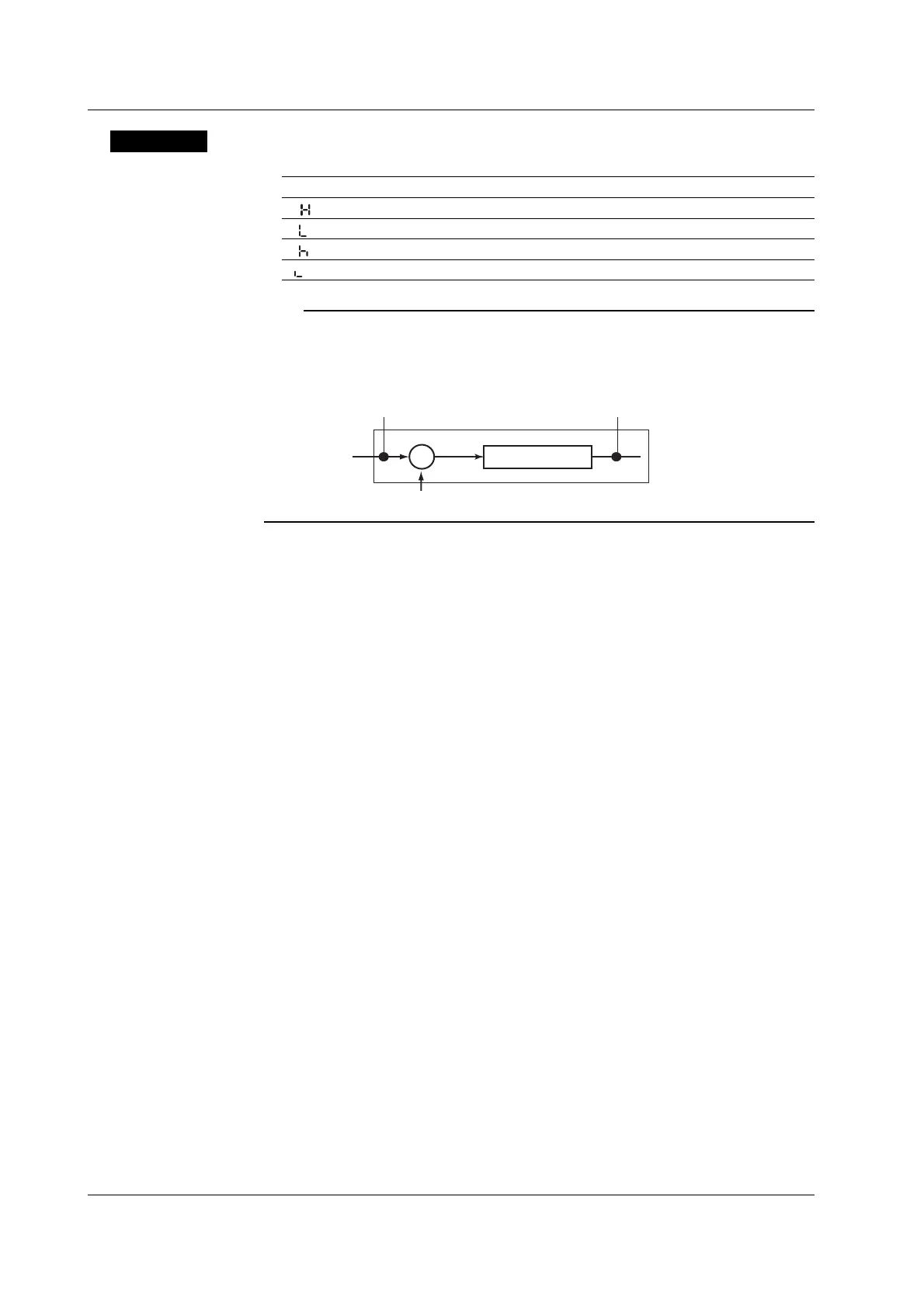
On channels set to delta computation, alarms can be detected on the values illustrated in the
figure below.
Input value
Measured value on the reference channel
Alarm on a channel set to delta computation
Alarm
H, L
Alarm
h, l
Measured value
−
Alarm Value
• High Limit Alarm/Low Limit Alarm
The following values can be specified.
• For DC voltage, thermocouple, or RTD:
Values within the measurable range in the input range (example: –2.000 to
2.000 V for the 2 V input range).
• For ON/OFF input (DI): 0 or 1.
• For linear scaling (1-5V, scaling, and square root):
A value within –5 to 105% of the scaling span and within the range of
–19999 to 30000 (excluding the decimal point).
• Difference High Limit Alarm/Difference Low Limit Alarm
Values in the measurable range can be specified.Measurable range refers to
“Selectable Span Range” in the table on page 2-5.
Relay No.
The selectable relay numbers are listed below.
I01 and I02 on the /A1 option
I01, I02, I03, and I04 on the /A2 option
I01, I02, I03, I04, I05, and I06 on the /A3 option
<Related Topics> Setting the auxiliary alarm function: Section 4.1
2.2 Setting the Alarm
 Loading...


