1-2
IM 04P03B01-01E
For the procedure to set the functions, see section 1.6, “Function Setup Guide.”
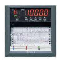
• Delta Computation
The value obtained by subtracting the measured value of another channel (called the
reference channel
) from the input value of the channel set to delta computation is used
as the measured value of that channel. The reference channel must be assigned to a
channel whose channel number is less than that of the channel on which delta
computation is specified. The channel on which delta computation is specified is
automatically set to the same range type as the reference channel.
Input
value
Measured value on the reference channel
Channel set to delta computation
Measured value
–
Note
A channel whose input type is set to DC voltage, TC, or RTD can be designated as a
reference channel. However, channels set to scaling or square root computation cannot be
designated.
• Scaling
The input values are scaled to values in the appropriate unit to be used as measured
values.
0 V −100.0°C
10 V
300.0°C
Measured valueInput value
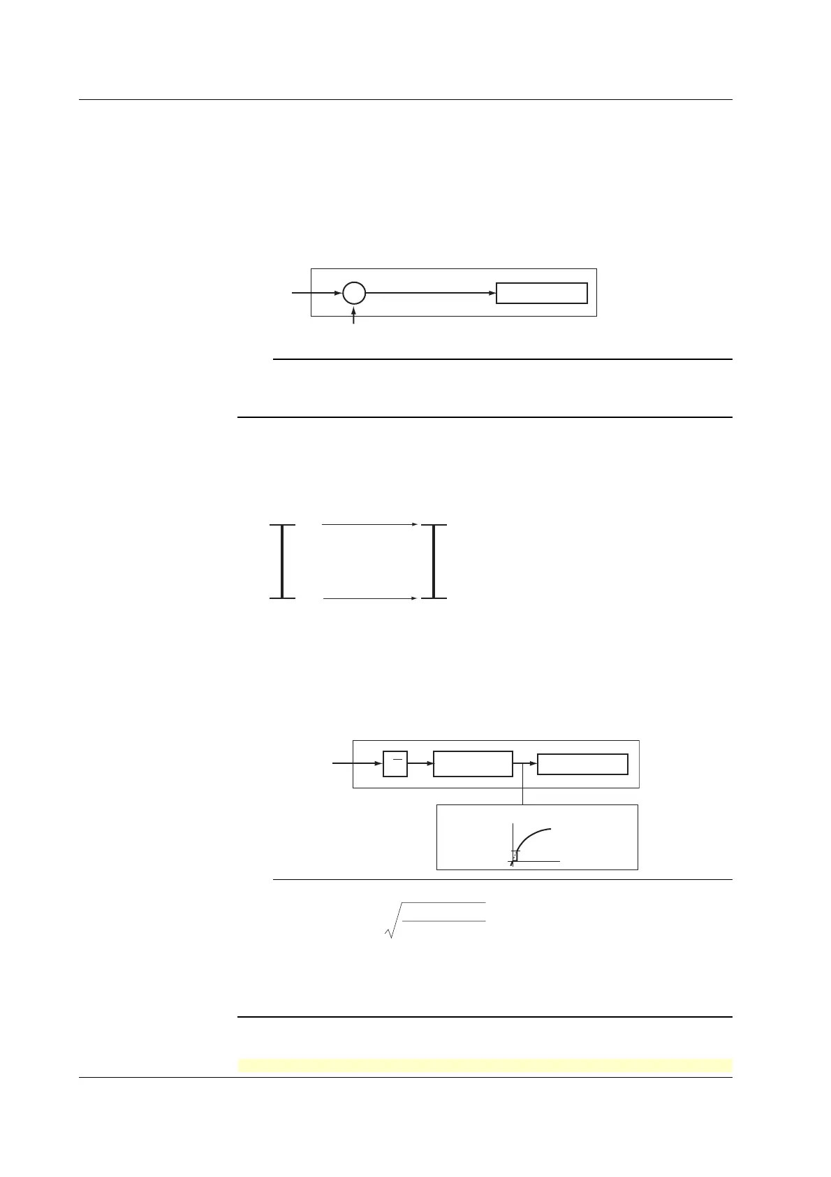
• Square Root Computation
When the input type is DC voltage, the square root of the input value is calculated, the
result is scaled to a value in the appropriate unit, and used as the measured value of
the channel. Also, the low-cut function (input less than a given measured value is
fixed to 0% (scale left value)) can be used.
Input value
Input value
Low-cut value
Result of square
root computation
Measured value
Channel set to square root computation
Measured value
√
Scaling
Note
The square root computation on the recorder uses the following formula.
F = ( F - F )
V - V
V - V
+ F
x
x
max
max min
min min
min
where V
min
(leftmost value of span) < V
max
(rightmost value of span)
F
min
(leftmost value of scale after scaling) < F
max
(rightmost value of scale after
scaling)
V
x
is the input voltage and F
x
is the scaled value
<Related Topics> Setting the input range: Section 5.1
1.1 Measuring Input Section
 Loading...


