Maintenance & Technical Specifications 3 - 9
Digital Scanner Signal Descriptions
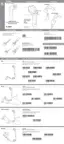
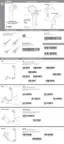
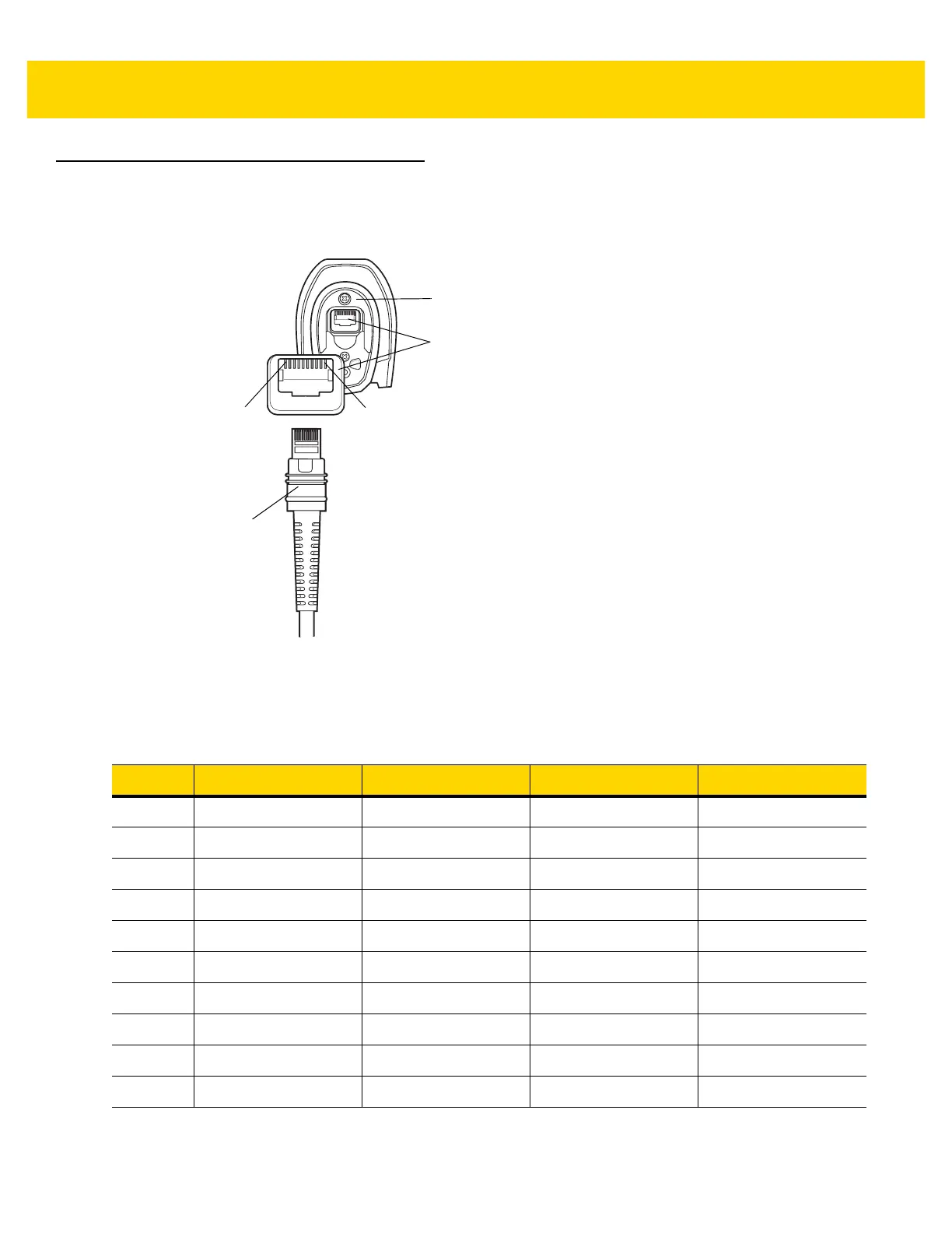
Figure 3-1 Digital Scanner Cable Pin-outs
The signal descriptions in Table 3-3 apply to the connectors on the DS3608 digital scanner and are for reference
only.
Table 3-3 DS3608 Digital Scanner Signal Pin-outs
Pin USB RS-232 Keyboard Wedge IBM
1
Cable ID Cable ID Cable ID Cable ID
2
Power (+5V) Power (+5V) Power (+5V) Power (+5V)
3
Ground Ground Ground Ground
4
IBM_OUT TxD KeyClock Reserved
5
IBM_IN RxD TermData D +
6
IBM_T/R RTS KeyData Reserved
7
Reserved CTS TermClock D -
8
Reserved Reserved Reserved Reserved
9
Reserved Reserved Reserved Reserved
10
Power (+12V) Power (+12V) Power (+12V) Power (+12V)
Cable Interface Port
PIN 10
PIN 1
Interface Cable
Modular Connector
Bottom of Scanner

 Loading...