P1036102-007 ZXP Series 7 Card Printer Service Manual 219
Replacement Procedures for the Laminator
Removal Sequence
Removal Sequence
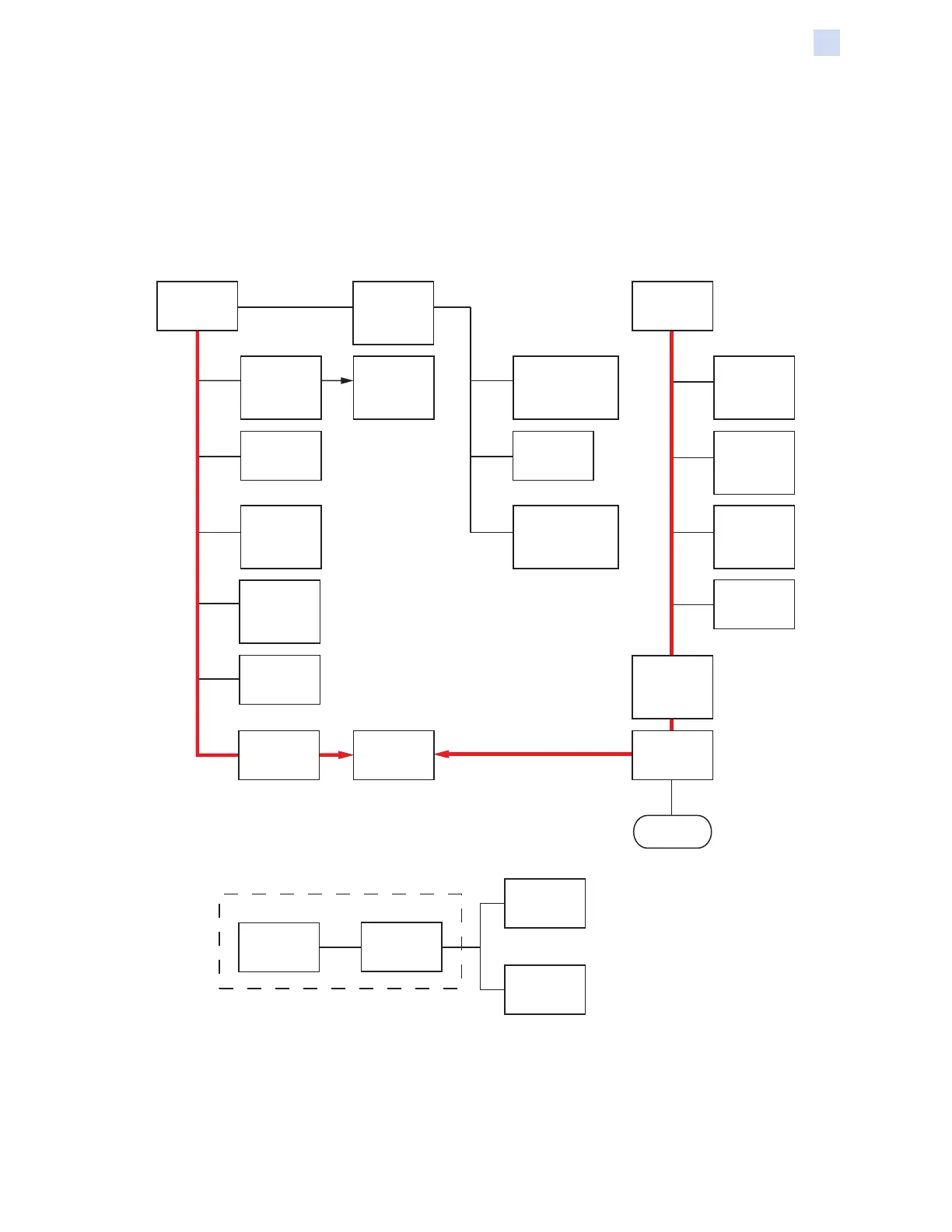
The following figures show the recommended removal sequence. For each item,
follow the diagram to see what must be removed for access.
To remove the Exit Rollers (page 279), first remove the 24V Heater Fans (page
246), then open the Laminator Door, and remove the Laminator Heater Assembly
(page 242) and the Front Frame (page 259) -- follow the red paths.
24V Heater
Fans
(Page 246)
Motor
and Plate
Assembly
(Page 248)
Top Laminator
Control Motor
(Page 254)
Card Entry
Sensor Cable
Assembly
(Page 285)
Door Sensor
Cable
Assembly
(Page 288)
24V Heater
Fans
(Page 246)
24V Heater
Fans
(Page 246)
Exit Rollers
(Page 279)
Bottom
Laminator
Control Motor
(Page 255)
Media
Authentication
Antenna PCBA
(Page 257)
Staging Motor
(Page 256)
Media
Authentication
Antenna PCBA
(Page 257)
Molded
Ribbon
Spindle
(Page 240)
Square
Corner
Spindle
(Page 241)
Halogen
Bulbs
(Page 243)
Laminator
Heater
Assembly
(Page 242)
Front Frame
(Page 259)
Laminator
Controller
PCBA
(Page 251)
Open
Laminator
Door
Next Page
Remove the
baseplate from
the Frame and
Base Assembly
Separate the
Frame from
the Base
Frame
Frame
 Loading...
