220 Actual signals and parameters
OVERFLOW Counter moves between the minimum and maximum limits
and rolls over to the opposite limit, when either the minimum
or maximum limit is reached.
Minimum and maximum limits are set by parameters 1905
COUNTER LIMIT and 1908 COUNTER RES VAL. Greater
value from the two will be set as the maximum and the other
as the minimum.
When parameter 1909 COUNT DIVIDER or either of the
limits is changed so that the change causes the value of
parameter 0166 COUNTER VALUE to be outside of the
min/max limits, the counter is assigned to the closest limit
value.
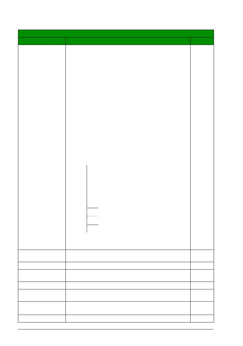
Example: If the limits are set as shown in the figure below,
the value of parameter 0166 COUNTER VALUE changes as
follows:
• Counting up: …
–
> 19998
–
> 19999
–
> 20000
–
> 100
–
>
101
–
> 102 …
• Counting down: …
–
> 102
–
> 101
–
> 100
–
> 20000
–
>
19999
–
> 19998 …
When 0166 COUNTER VALUE is equal to 1905 COUNTER
LIMIT, the counter limit values trigger state changes.
10
1908 COUNTER
RES VAL
Defines the value for the counter after reset. 0
0…65535 Counter value 1 = 1
1909 COUNT
DIVIDER
Defines the divider for the pulse counter. 0
0…12 Pulse counter divider N. Every 2
N
bit is counted. 1 = 1
1910 COUNT
DIRECTION
Defines the source for the counter direction selection. UP
DI1(INV) Counter direction selection through inverted digital input
DI1. 1 = counts up, 0 = counts down.
-1
DI2(INV) See selection DI1(INV).-2
All parameters
No. Name/Value Description Def/FbEq
0
100
1908 COUNTER RES VAL
1905 COUNTER LIMIT
20000
0166 COUNTER VALUE
65535

 Loading...


