Parameters 303
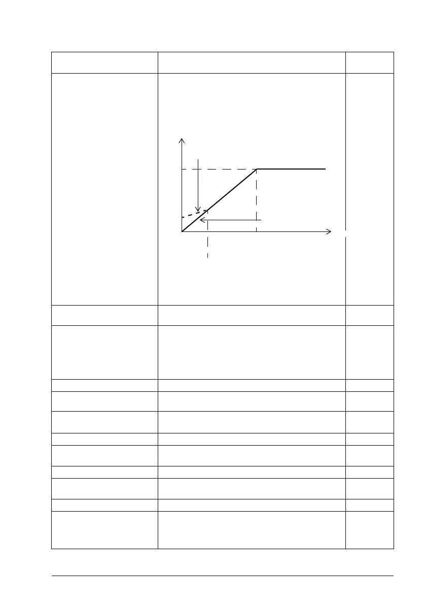
97.13 IR compensation Defines the relative output voltage boost at zero speed (IR
compensation). The function is useful in applications with
a high break-away torque where vector control cannot be
applied.
See also section IR compensation for scalar motor control
on page 69.
3.50%
0.00…50.00% Voltage boost at zero speed in percent of nominal motor
voltage.
1 = 1%
97.15 Motor model
temperature
adaptation
Selects whether the temperature-dependent parameters
(such as stator or rotor resistance) of the motor model
adapt to actual (measured or estimated) temperature or
not.
See parameter group 35 Motor thermal protection for
selection of temperature measurement sources.
Disabled
Disabled Temperature adaptation of motor model disabled. 0
Estimated temperature Estimated temperature (35.01 Motor estimated
temperature) used for adaptation of motor model.
1
97.16 Stator temperature
factor
Tunes the motor temperature dependence of stator
parameters (stator resistance).
50
0.00…200.00% Tuning factor.
97.17 Rotor temperature
factor
Tunes the motor temperature dependence of rotor
parameters (eg. rotor resistance).
100
0.00…200.00% Tuning factor.
97.20 U/F ratio Selects the form for the U/f (voltage to frequency) ratio
below field weakening point. For scalar control only.
Disabled
Linear Linear ratio for constant torque applications. 0
Squared Squared ratio for centrifugal pump and fan applications.
With squared U/f ratio the noise level is lower for most
operating frequencies. Not recommended for permanent
magnet motors.
1
No. Name/Value Description Default
FbEq 16
U / U
N
(%)
f (Hz)
Field weakening point
Relative output voltage. No
IR compensation.
Relative output voltage. IR
compensation set to 15%.
15%
100%
50% of nominal
frequency

 Loading...


