438 Fieldbus control through a fieldbus adapter
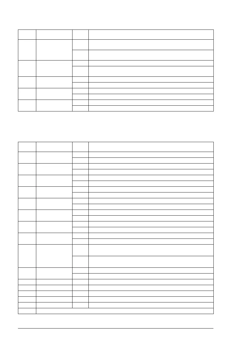
Contents of the fieldbus Status word
The upper case boldface text refers to the states shown in the state diagram on
page 439.
11 Ext ctrl loc 1 Select External Control Location EXT2. Effective if control
location is parameterized to be selected from fieldbus.
0 Select External Control Location EXT1. Effective if control
location is parameterized to be selected from fieldbus.
12 User bit 0 1 TBA
0 Writable control bits that can be combined with drive logic for
application-specific functionality.
13 User bit 1 1 TBA
0TBA
14 User bit 2 1 TBA
0TBA
15 User bit 3 1 TBA
0TBA
Bit Name Value State/Description
0 Ready to switch
ON
1 READY TO SWITCH ON.
0 NOT READY TO SWITCH ON.
1 Ready run 1 READY TO OPERATE.
0 OFF1 ACTIVE.
2 Ready ref 1 OPERATION ENABLED.
0 OPERATION INHIBITED.
3 Tripped 1 FAULT.
0No fault.
4 Off 2 inactive 1 OFF2 inactive.
0 OFF2 ACTIVE.
5 Off 3 inactive 1 OFF3 inactive.
0 OFF3 ACTIVE.
6Switch-on
inhibited
1 SWITCH-ON INHIBITED.
0–
7 Warning 1 Warning active.
0 No warning active.
8 At setpoint 1 OPERATING. Actual value equals reference = is within
tolerance limits (see parameters 46.21…46.23).
0 Actual value differs from reference = is outside tolerance
limits.
9 Remote 1 Drive control location: REMOTE (EXT1 or EXT2).
0 Drive control location: LOCAL.
10 Above limit - See bit 10 of 06.17 Drive status word 2.
11 User bit 0 - See parameter 06.30 MSW bit 11 selection.
12 User bit 1 - See parameter 06.31 MSW bit 12 selection.
13 User bit 2 - See parameter 06.32 MSW bit 13 selection.
14 User bit 3 - See parameter 06.33 MSW bit 14 selection.
15 Reserved
Bit Name Value State/Description

 Loading...