40 Control macros
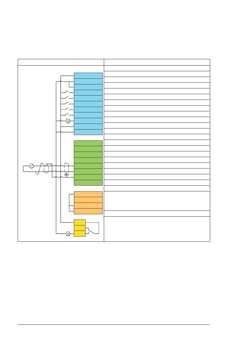
Default control connections for the Motor potentiometer macro
This connection diagram is valid for drives with the standard drive variant
ACS380-04xS and the configured drive variant ACS380-04xC +L538 (with the Motor
potentiometer macro selected).
Notes:
Terminal sizes: 0.14 mm² … 1.5 mm²
Tightening torque: 0.5 N·m (0.4 lbf·ft).
Terminals DGND, AGND and SGND are internally connected to same reference
potential.
1)
When the input signal is on, the speed/frequency increase or decrease along a
parameter-defined change rate. See parameters 22.75, 22.76 and 22.77. If D3 and
DI4 are both active or inactive, the frequency/speed reference is unchanged. The
existing frequency/speed reference is stored during stop and power down.
Terminals Description
Digital I/O connections
Aux. +24 V DC, max 200 mA
Aux. voltage output common
Digital input common
Stop (0) / Start (1)
Forward (0) / Reverse (1)
Speed / freq up
1)
Speed / freq down 1)
Constant speed sel 1
Ready run (0) / Not ready run (1)
Digital output auxiliary voltage
Digital input/output common
Analog I/O
Not configured
Analog input circuit common
Not configured
Analog input circuit common
Not configured
Analog output circuit common
Signal cable shield (screen)
Ref. voltage +10 V DC
Safe torque off (STO)
Safe torque off. Connected at factory.
Drive starts only if both circuits are closed.
Relay output
No Fault [Fault (-1)]
Max. 500 ohm
+24V
DGND
DCOM
DI1
DI2
DI3
DI4
DIO1
DIO2
DIO SRC
DIO COM
AI1
AGND
AI2
AGND
AO
AGND
SCR
+10V
S+
SGND
S1
S2
RC
RA
RB

 Loading...


