2.4 Electrical Installation Chapter 2: Installation
42 493-0736-11 (6-2)
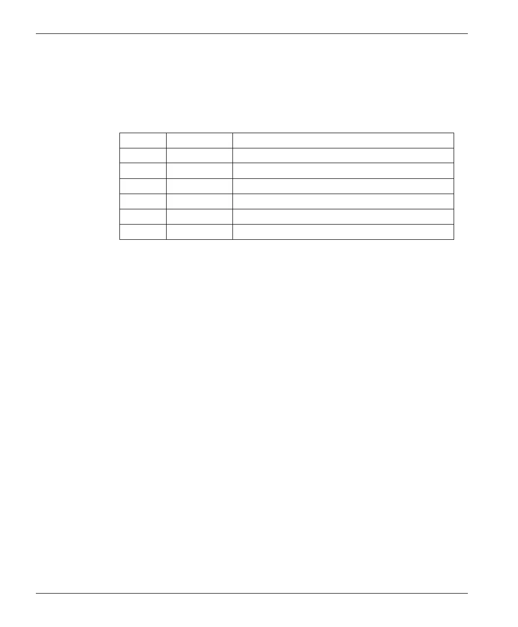
Figure 25 shows an example of a single controller current loop. It is assumed that
all the units are isolated from supply ground. This type of current loop must
always be grounded at one single point so that it does not float away from ground
and introduce a large interference potential. Table 2 shows the potential at points
1 to 6 with respect to ground, and indicates which points are suitable for
grounding.
Table 2 Grounding Points.
Point Potential Grounding Possibility
1 –10 V Not permitted, max CMV = 0V
2 –5 V Not permitted, max CMV = 0V
3 0 V Permitted
4 +5 V Permitted
5 +10 V Permitted
6 +38 V Not permitted, max CMV = +17 V