Defining the base frame orientation and start window start calibration
The base frame quaternion defines where the 0.0 rad point is for the robot motion.
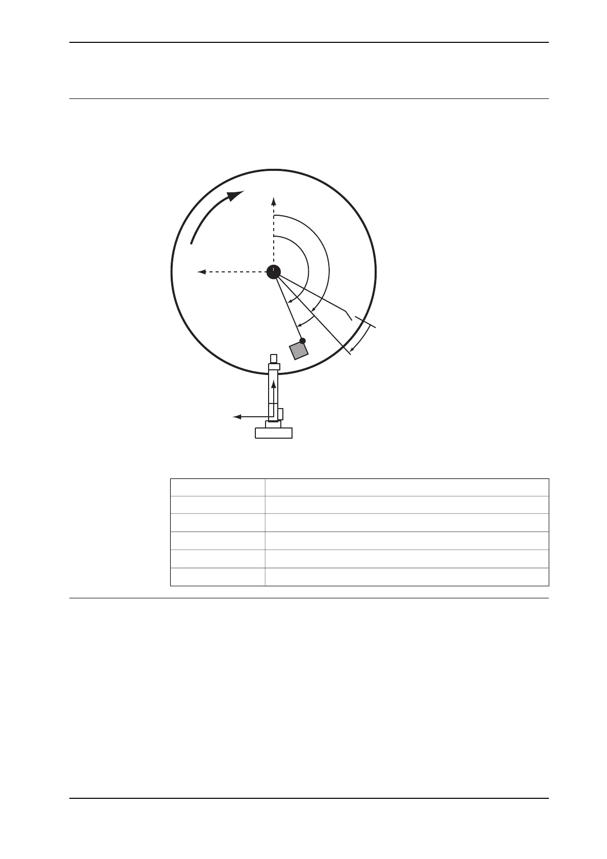
The following figure shows an example of the angles that are used when defining
the base frame orientation for the circular conveyor.
IRB
S
0.0 rad
R
X
IRB
Y
IRB
p_centre, X,
Y
p_0, X_0, Y_0
Q
θ
P
θ
Base
θ
TP
θ
xx1200001103
Direction of rotationR
Synchronization switchS
Queue tracking distance angleQ
θ
Angle shown on FlexPendantTP
θ
Angle calculated from p_0 positionP
θ
Base frame angle to be converted to a quaternionBase
θ
Calculating the x and y positions for the base frame
Use this procedure to calculate the x and y positions for the base frame.
1 Use Wobj0 on the FlexPendant. Pick out a reference point on the circular
conveyor, jog the TCP to this point and record p_0.
2 Run the conveyor to another position. Jog the TCP to the reference point
and record p_1.
3 Run the conveyor to a third position, jog the TCP to the reference point and
record p_2.
4 Use the function CNVUTL_cirCntr with the points p_0, p_1, and p_2, to
calculate the center of the circle, p_centre.
The system module cnv_utl.sys can be found in Robotware.
Continues on next page
Application manual - PickMaster® Twin - PowerPac 213
3HAC064218-001 Revision: B
© Copyright 2021 ABB. All rights reserved.
4 Working with PickMaster PowerPac
4.3.5.3 Defining the base frame (IRC5)
Continued
 Loading...


