differences presented in the monitored data view. These values should be within the
permitted tolerances, that is, close to zero.
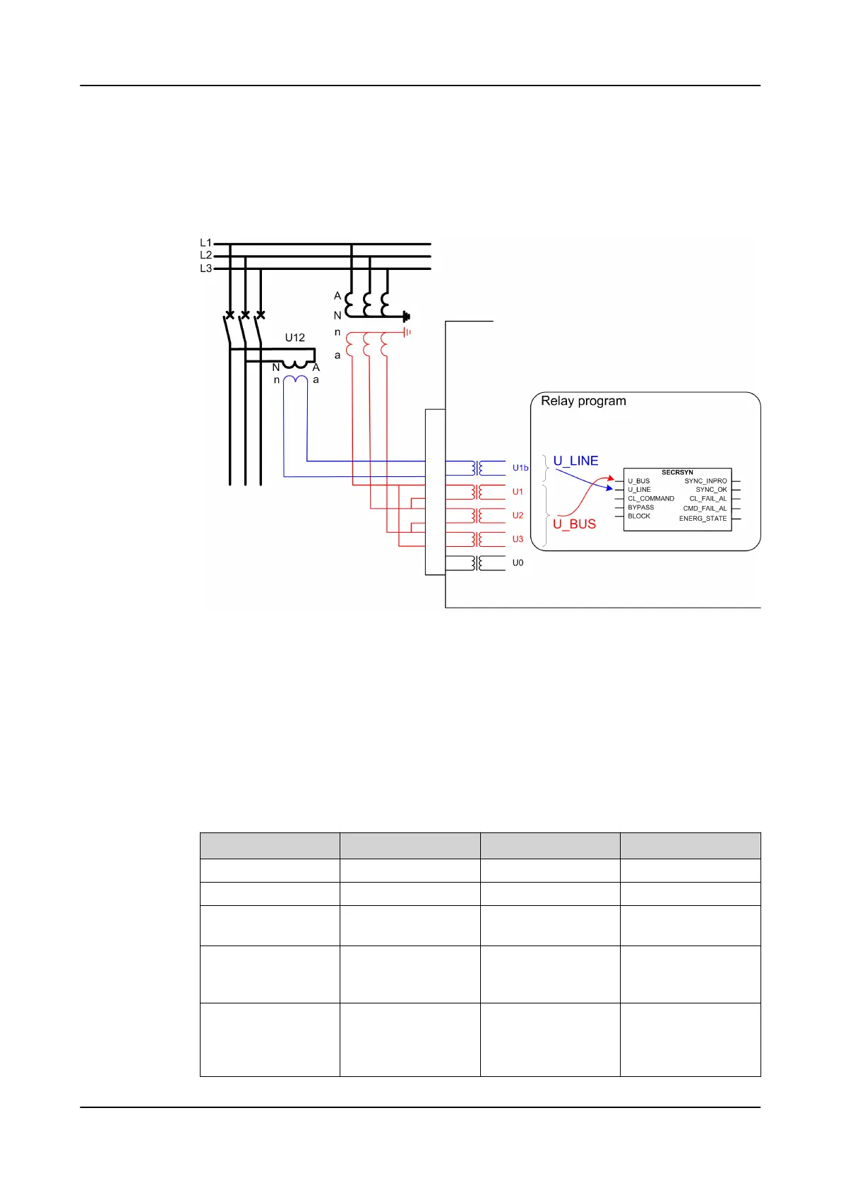
Figure 323
shows an example where the synchrocheck is used for the circuit breaker
closing between a busbar and a line. The phase-to-phase voltages are measured
from the busbar and also one phase-to-phase voltage from the line is measured.
Figure 323: Connection of voltages for the protection relay and signals used in
synchrocheck
9.3.6 Signals
9.3.6.1 SECRSYN Input signals
Table 674: SECRSYN Input signals
Name Type Default Description
U_BUS SIGNAL 0 Busbar voltage
U_LINE SIGNAL 0 Line voltage
CL_COMMAND BOOLEAN 0=False External closing re-
quest
BYPASS BOOLEAN 0=False Request to bypass
synchronism check
and voltage check
BLOCK BOOLEAN 0=False Blocking signal of the
synchro check and
voltage check func-
tion
Control functions 1MRS758755 C
652 REC615 & RER615
Technical Manual

 Loading...


