-EN Rev. E Operating instruction SCK Gas Sampling System 155
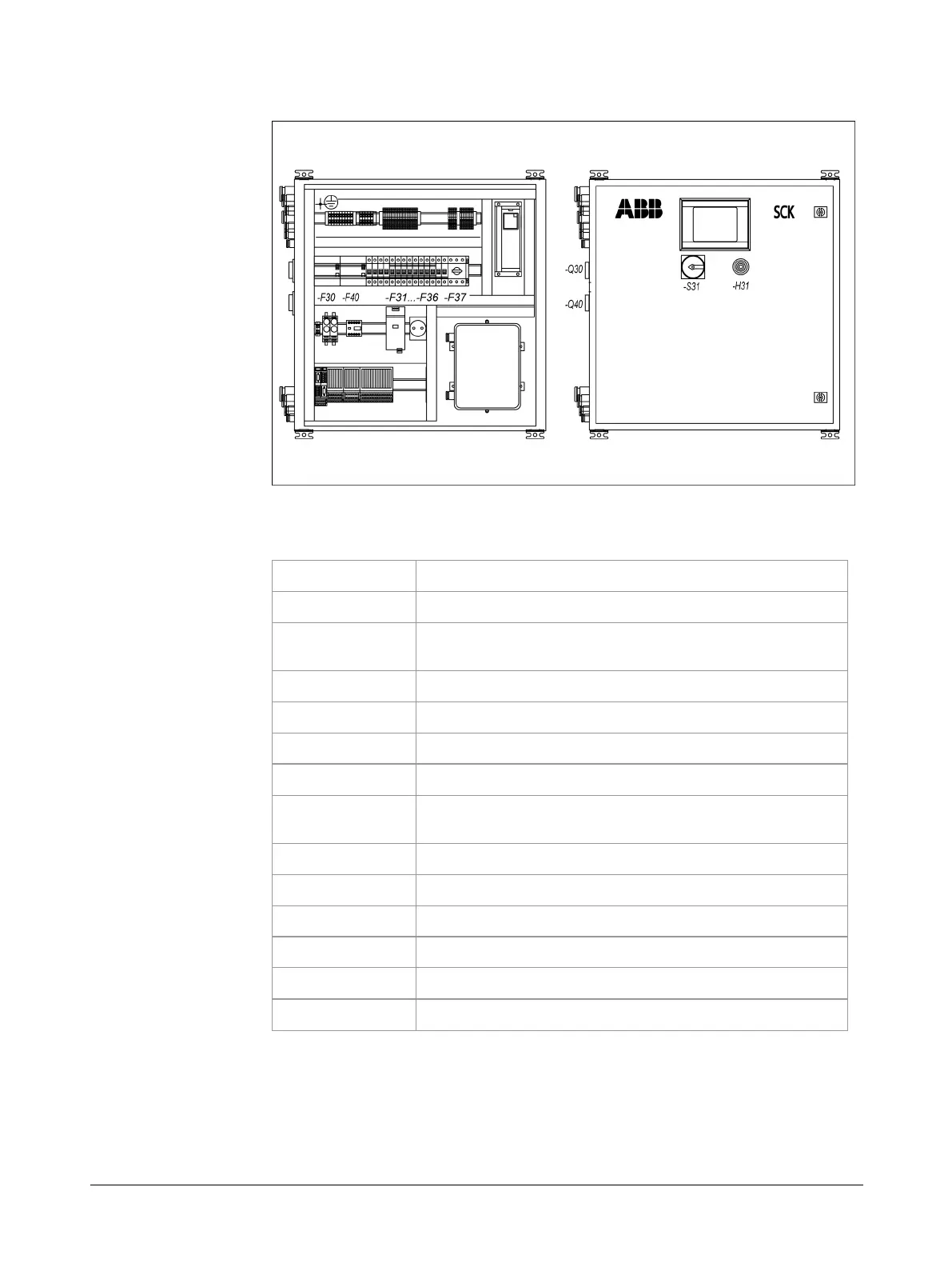
Diagram of the location of maintenance-relevant equipment on the control
cabinet (open left, closed right):
The following table lists the above-mentioned equipment:
Equipment ID Designation
-H31
Warning buzzer
-F30
Residual current circuit breaker (for main switch; op-
tional)
-F40
Residual current circuit breaker (for UPS; optional)
-F31
Service socket circuit breaker
-F32
Power supply circuit breaker 24V
-F33
Probe heating circuit breaker
-F34
Sample gas line/connection box/230 V valves heating
circuit breaker
-F35
Heat exchanger circuit breaker
-F36
Cooling-water pump circuit breaker
-F37
Cooling-water pump motor breaker
-S31
Service switch
-Q30
Main switch for normal voltage
-Q40
Main switch for UPS (optional)