SensyMaster FMT430, FMT450 THERMAL MASS FLOWMETER | OI/FMT430/450-EN REV. B 59
Digital output 41 / 42, 51 / 52 (basic device)
Can be configured as pulse, frequency or binary output via on-
site software.
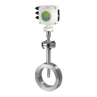
Digital output 41 / 42, 51 / 52 passive as a pulse of frequency output
Passive digital output 51 / 52 as binary output
Figure 46: (I = internal, E = external, R
B
= load)
Pulse / frequency output (passive)
/ 42, 51 / 52
V ≤ U
CEL
≤ 3 V
< 2.5 kHz: 2 mA < I
CEL
< 30 mA
For f > 2.5 kHz: 10 mA < I
CEL
< 30 mA
V ≤ U
CEH
≤ 30 V DC
≤ I
≤ 0.2 mA
to 2000 ms
V ≤ U
CEL
≤ 3 V
V ≤ U
CEH
≤ 3 V DC
≤ I
≤ 0.2 mA
Can be configured using software.
Menu: Input/Output on page 113
Note
• Terminals 42 / 52 have the same potential. Digital outputs
DO 41 / 42 and DO 51 / 52 are not electrically isolated from
each other. If an additional electrically isolated digital output
is required, a corresponding plug-in module must be used.
• If you are using a mechanical counter, we recommend setting
a pulse width of ≥ 30 ms and a maximum frequency of
f
max
≤ 30 Hz.
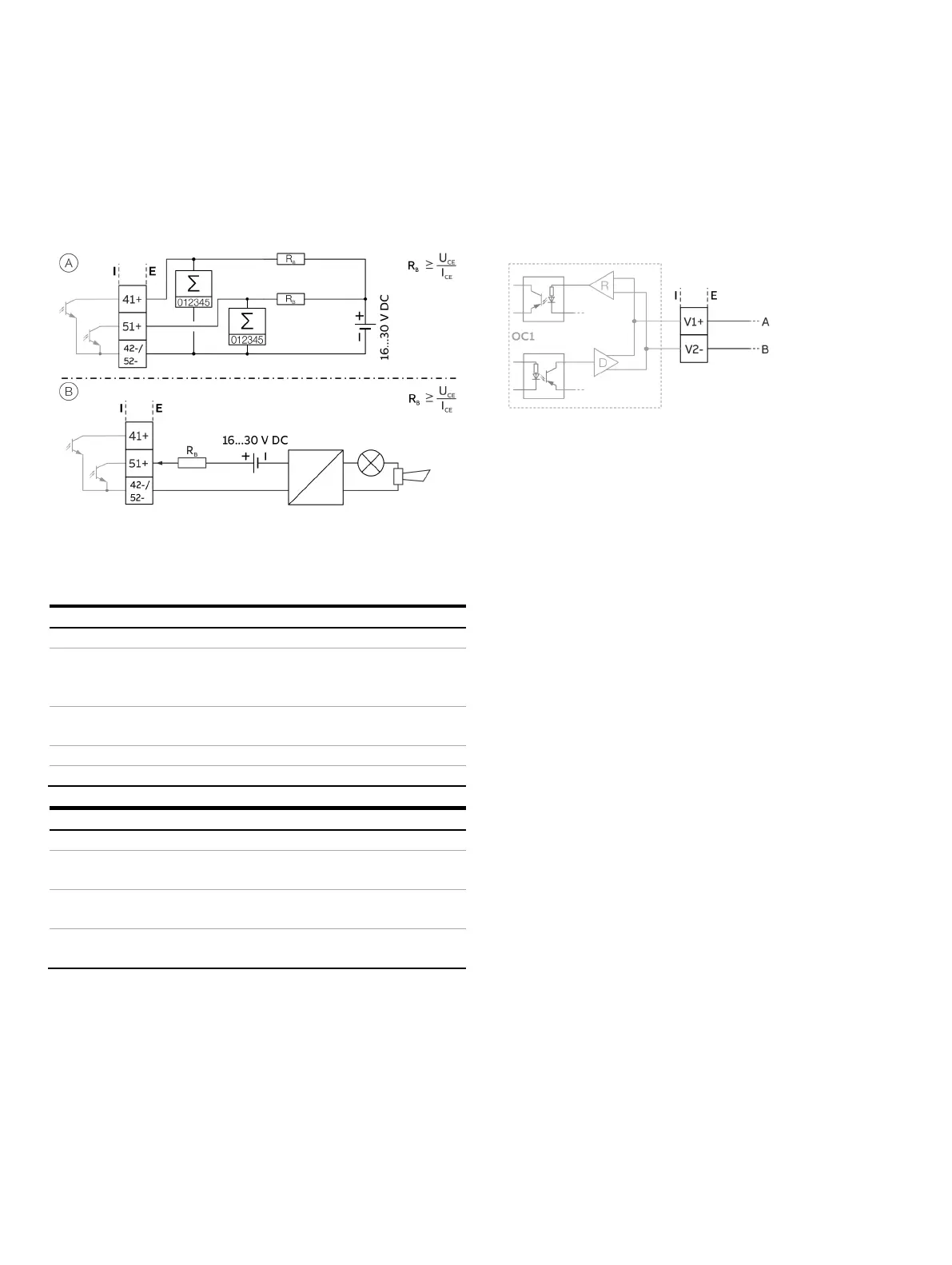
Modbus® / PROFIBUS DP® interface V1 / V2 (plug-in card)
A Modbus or PROFIBUS DP interface can be implemented by
using the ‘Modbus RTU, RS485 (white)’ or ‘PROFIBUS DP, RS485
(white)’ plug-in cards.
Figure 47: Plug-in card as a Modbus / PROFIBUS DP interface (I = internal, E = external)
The corresponding plug-in card can only be used in slot OC1.
For information on communication through the Modbus or
PROFIBUS DP protocols, refer to chapters Modbus®
communication on page 69 and PROFIBUS DP® communication
on page 70.