60 SensyMaster FMT430, FMT450 THERMAL MASS FLOWMETER | OI/FMT430/450-EN REV. B
… 7 Electrical connections
… Electrical data for inputs and outputs
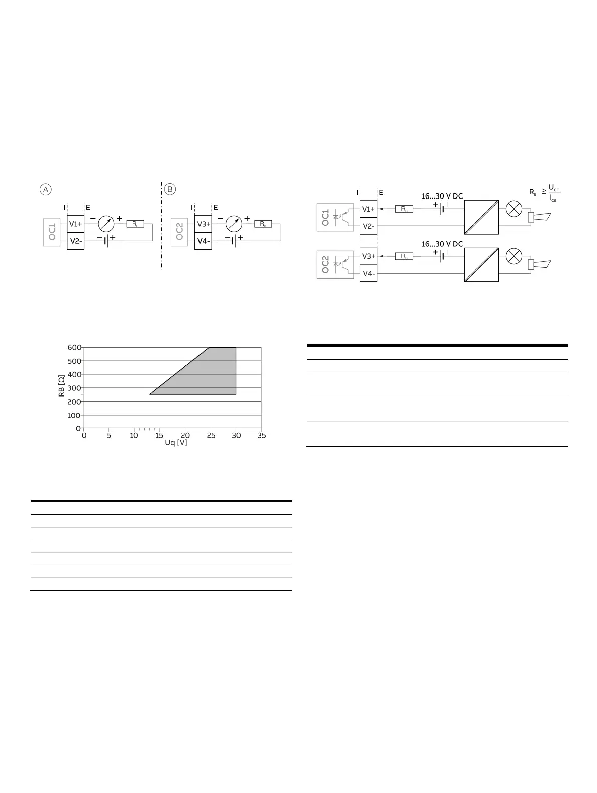
Current output V1 / V2, V3 / V4 (plug-in module)
Up to two additional plug-in modules can be implemented via
the ‘Passive current output (red)’ option module.
Can be configured for outputting mass flow, volume flow,
density and temperature via on-site software.
Current output V1 / V2, passive
Current output V3 / V4, passive
Figure 48: (I = internal, E = external, R
B
= load)
The plug-in module can be used in slot OC1 and OC2.
Permissible source voltage U
q
for passive outputs in relation to load
resistance R
B
where Imax = 22 mA.
Figure 49: Source voltage for passive outputs
/ V2, V3 / V4
Ω ≤ R
≤ 600 Ω
0.1 % of measured value
* The source voltage U
q
is dependent of the load R
B
and must be placed in
an additional area.
Digital output V1 / V2, V3 / V4 (plug-in module)
An additional binary output can be implemented via the ‘Passive
digital output (green)’ plug-in module.
Can be configured as an output for flow direction signaling,
alarm output etc. via on-site software.
Figure 50: Plug-in card as binary output (I = internal, E = external, R
B
= load)
The plug-in module can be used in slot OC1 or OC2.
V ≤ U
CEL
≤ 3 V
mA < I
< 30 mA
V ≤ U
CEH
≤ 30 V DC
Can be configured using software.
Menu: Input/Output on page 113