EasyManua.ls Logo

Abov MC97F6108A - Figure 49. Auto Period Mode Block Diagram (ATPSEL = 2 B1 X); PPG Period When ATPSEL = 2 B1 X

Default Icon
256 pages
To Next Page IconTo Next Page
To Previous Page IconTo Previous Page
Loading...
MC97F6108A User’s manual 11. PPG (Programmable Pulse Generator)
107
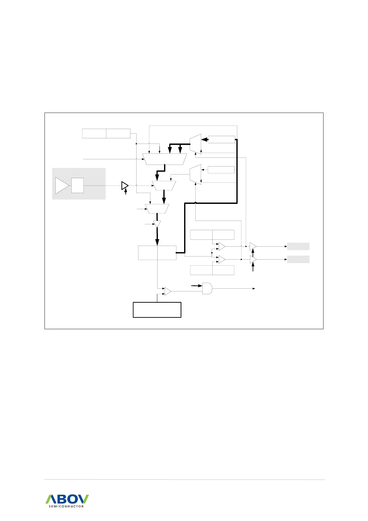
11.8.4 PPG period when ATPSEL = 2'b1x
When comparator 2 outputs low and ATPSEL is 2'b1x, ATPHR/ATPLR (the period register in auto
period mode) is increased by USTEP and it is applied to the next cycle.
NOTE: ATPEN should be set to '1' before writing a value in a period register (ATPHR, ATPLR). Otherwise the cycle
starts with the increased period value by USTEP.
{PPGH, PPGL}
(16-bit Counter)
ATPRL
(8-bit)
0 1
MUX
- DSTEP[7:0]
00 01 10 11
MUX
CPOUT2
(in the previous period)
current period
increase
decrease
ATPSEL[1:0]
ATPEN
0 1
MUX
PPGPL
(8-bit)
PPG start
read only
PPG period register
PERIOD write
M 0
U
X 1
M 0
U
X 1
ATPMAXHR
(8-bit)
ATP_MAX
ATPEN
~(PERIOD write)
MAX match
MIN match
current period
current period
ATPEN
PPGPH
(8-bit)
ATPMAXHR
(8-bit)
ATPMINHR
(8-bit)
ATPMINHR
(8-bit)
ATPRH
(8-bit)
period matching
CMP2
C2DBSEL[1:0]
by pass
0.3 us
0.6 us
1.2 us
+ USTEP[7:0]
ATP_MIN
Figure 49. Auto Period Mode Block Diagram (ATPSEL = 2'b1x)

Table of Contents

Related product manuals